You can provide hot water supply in your house or apartment in many ways, but direct heating, for example with a direct-flow electric heater or boiler, is not the best effective way. The DHW plate heat exchanger has proven itself to be excellent in simplicity and reliability. If there is a heat source, e.g. independent heating or even centralized, then it is quite reasonable to take the heat for heating water from them, without wasting expensive electricity for these purposes.
Design and principle of operation
A plate heat exchanger (PHE) ensures the transfer of heat from a heated coolant to a cold one, without mixing them, decoupling the two circuits from each other. The coolant can be steam, water or oil. In the case of hot water supply, the heat source is often the heating fluid of the heating system, and the heated medium is cold water.
Structurally, the heat exchanger is a group of corrugated plates assembled parallel to each other. Between them, channels are formed through which the coolant and the heated medium flow, and they alternate layer by layer without mixing. By alternating layers through which fluids of both circuits flow, the heat exchange area increases.
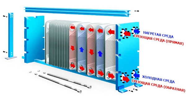
Heat exchanger operating diagram
The corrugation of the bowl is performed in the form of waves, moreover, oriented so that the channels of one circuit are located at an angle to the channels of the second circuit.
The connections of the inputs and outputs are made so that the liquids flow towards each other.
The surface and material of the plates are selected based on the required heat transfer power and the type of coolant. In particularly efficient and sophisticated heat exchangers, the surface is shaped to generate vortices near the surface of the plate, increasing heat transfer without creating much resistance to the overall current.
The heat exchanger is connected between two circuits:
- In series with the heating system or in parallel with the presence of control valves.
- To the inlet from the cold water supply and the outlet to the DHW consumer.
Cold water flowing through the heat exchanger is heated by heat from the heating system to the required temperature and supplied to the consumer tap.
Main characteristics of plate heat exchanger:
- Power, W;
- Maximum coolant temperature, oC;
- Throughput, productivity, liters/hour;
- Hydraulic resistance coefficient.
The power depends on the total heat exchange area, the temperature difference in both circuits between the input and output, and even on the number of plates.
The maximum temperature is set by the selection of materials and the method of connecting the plates and the heat exchanger body.
The throughput increases with the number of plates, since they are connected virtually in parallel, each new pair of plates adds an additional channel for fluid flow.
The coefficient of hydraulic resistance is important when calculating the load on the heating system, where the choice of a circulation pump depends on it, and is also important for other heat sources. Depends on the type of corrugation of the plates and the cross-sectional size of the channels and their number.
It is based on these parameters that a heat exchanger is ultimately selected for a specific situation. Most often, plate heat exchangers have a collapsible design, in which you can increase or decrease the number of plates and choose their type and size. The power and performance of the heat exchanger must be sufficient to heat running cold water without creating a critical load on the heating system.
For the most popular cases, what is the security hot water For private households, houses or apartments, ready-made heat exchangers with constant characteristics are produced.
Calculation
Selecting a suitable heat exchanger is difficult to do based on its power alone or throughput. The efficiency of DHW preparation depends on the condition of the coolant in the primary circuit and in the second, on the material and design of the heat exchanger, the speed and mass fraction of the coolant passing per unit time through the plate heat exchanger. However, naturally, you should first perform a calculation that allows you to arrive at a certain combination of power and performance in order to select the appropriate model.
Basic data required for calculation:
- Type of medium in both circuits (water-water, oil-water, steam-water)
- Temperature of the coolant in the heating system;
- The maximum permissible decrease in coolant temperature after passing through the heat exchanger;
- Initial temperature of water used for hot water supply;
- Required DHW temperature;
- Target hot water consumption in maximum consumption mode.
In addition, the calculation formulas include the specific heat capacity of the liquid in both circuits. Used for DHW table value for the initial water temperature, usually +20°C, equal to 4.182 kJ/kg*K. The specific heat capacity of the coolant should be determined separately if it contains antifreeze or other additives to improve its qualities. Likewise for central heating an approximate value or an actual value is taken based on data from the heating and communal services company.
The target flow rate is determined by the number of users for hot water and the number of devices (faucets, dishwasher, washing machine, shower) where it will be used. According to the requirements of SNiP 2.04.01-85, the following hot water flow rates are required:
- for the sink – 40 l/h;
- bathroom – 200 l/h;
- shower – 165 l/h.
The value for the sink is multiplied by the number of devices in the house that can be used in parallel, and added to the value for the bathtub or shower, depending on what is being used. For dishwasher and washing machine values are taken from the passport and instructions and only on condition that they support the use of hot water.
The second basic value is the power of the heat exchanger. It is calculated based on the obtained value of liquid flow and the difference in water temperatures at the inlet to the heat exchanger and at the outlet.
where m is water flow, C is specific heat capacity, Δt is the difference in water temperatures at the inlet and outlet of the PHE.
To obtain the mass flow rate of water, the flow rate expressed in l/h should be multiplied by the density of water 1000 kg/m3.
The efficiency of heat exchangers is estimated at 80-85%, and much depends on the design of the equipment itself, so the resulting value should be divided by 0.8(5).
On the other hand, the power limitation will be the calculation performed on the side of the primary circuit with the coolant, where, using the difference in permissible temperatures for the heating system, we obtain the maximum permissible power intake. The end result will be a compromise between the two values obtained.
If the power intake to heat the required amount of hot water is not enough, then it is wiser to use two heating stages and, accordingly, two heat exchangers. The power is distributed between them equally according to the required calculation. One stage performs preheating using the heating return from the low temperature. The second PHE already finally heats the water using hot water from the heating supply.
Strapping scheme
The heat exchanger is connected to the heating system in several ways. The simplest option with parallel connection and the presence of a control valve powered by a thermal head.
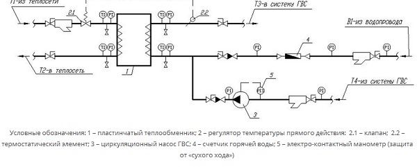
Shut-off ball valves at all terminals of the heat exchanger are mandatory in order to be able to completely shut off the access of liquid and provide conditions for dismantling the equipment. Power regulation and, accordingly, heating of hot water should be handled by a valve controlled by a thermal head. The valve is installed on the heating supply pipe, and the temperature sensor is installed on the outlet of the DHW circuit.
When organizing DHW cyclically with a storage tank, an additional tee is installed at the input of the heated circuit to turn on the cold tap water and DHW returns. Avoid unnecessary reverse current in the hot and cold water won't give check valve.
The disadvantage of this scheme is the greatly increased load on the heating system and inefficient heating of water in the second circuit with a larger temperature difference.
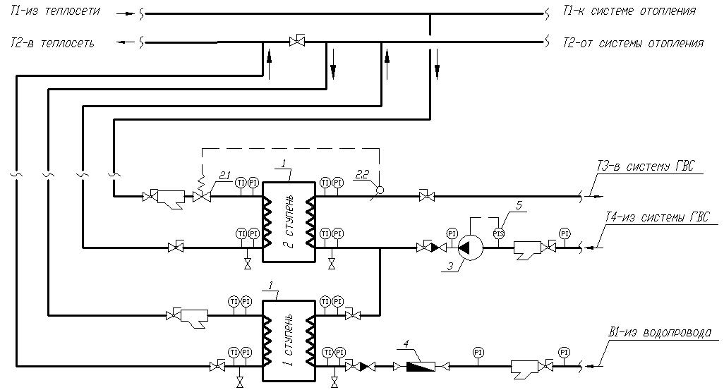
A two-stage scheme with two heat exchangers works much more productively and reliably.
1 – plate heat exchanger; 2 – direct-acting temperature regulator: 2.1 – valve; 2.2 – thermostatic element; 3 – circulation pump DHW; 4 – hot water meter; 5 – electric contact pressure gauge (protection against “dry running”)
The idea is to use two heat exchangers. In the first stage, the return of the heating system is used on one side, and cold water from the water supply on the other. This preheats to about 1/3 to half the desired temperature without sacrificing home heating. The circuit is switched on in series with the bypass, on which a needle valve is already attached, with the help of which the volume of the coolant is regulated.
The second PHE, the second stage, connected in parallel to the heating system - on the one hand, this is the supply of hot coolant from the boiler or boiler room, and on the other, hot water already heated at the first stage.
There is no need to adjust the first stage. Only ball valves are installed on all four outlets and a check valve for the cold water supply.
The second stage harness is identical parallel connection except that instead of cold water, already heated water from the first stage is connected.
Page 5 of 18
Schemes for connecting hot water supply to heating networks.
· In closed heating systems The coolant is completely returned to
source of heat supply (except for leaks). The coolant is used as a heating medium in heat exchangers. Closed systems are hydraulically isolated from heating networks, which ensures stable water quality in the hot water supply, because there is no removal of slag deposits into the hot water supply system (this is a plus). However, water enters the hot water supply system (into the pipes) from a cold water supply system, which is not subjected to deaeration (removal of oxygen and carbon dioxide), heats up and aggravates corrosion activity, therefore, pipes are destroyed faster from corrosion than in open circuits. Therefore, in closed systems it is recommended to use non-metallic, plastic pipes.
Closed circuits distinguish between single-stage and multi-stage. The choice of scheme depends on the ratio of heat consumption for heating and domestic hot water. The choice of connection scheme is made based on calculations.
· IN open systems DHW uses not only the heat supplied
coolant from the heating network to the local network, but also the coolant itself. In open circuits, hot water pipes corrode to a lesser extent than in closed systems, because water comes from the heating network after chemical water treatment (CWT), but stability may be disrupted sanitary standards water indicators. Open circuits are cheaper. Than closed, because no costs for heat exchangers and pumping equipment are required.
Schemes for connecting hot water supply systems of buildings to heating networks.
· Single-stage circuits (Fig. 7, 8):
One heat exchanger and heating for DHW occurs before the MOS).
Rice. 7. Single stage pre-connected
Rice. 8. Single stage parallel
· 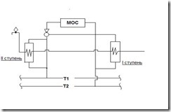 Multi-stage schemes (Fig. 9, 10):
Т = 30˚С Т = 5˚С
Rice. 9. Sequential two-stage

Rice. 10. Mixed two-stage
Two-stage schemes are effective in application because there is a deep decrease in the temperature of the return water, and there is also an independent heat consumption for heating and hot water supply, i.e. fluctuations in flow rate in the DHW system do not affect the operation of the MOS, which can occur in open circuits.
Installation of a hot water supply system is a labor-intensive process that requires certain knowledge and skills. In addition, each specific case has its own nuances. They should be taken into account so that the hot water supply is connected correctly.
Types of heating systems
Depending on the acceptable method of water supply, the source of water, the availability of various connection schemes, etc., everything heating networks can be divided into two types:
- closed heating networks;
- open type heating networks.
Let's take a closer look at what installation schemes exist within each of them.
Closed heating network diagram
Such complexes are mounted to centralized heating networks using hydroheat exchangers. There are several schemes for such hot water supply connection and each has its own characteristics.
- Parallel type.
This circuit is quite simple and includes only one temperature regulator. Water heating equipment and the network itself are focused on optimal DHW consumption. But this scheme has a significant drawback - the thermal efficiency of water is not fully realized. For example, the heat from network water is not used, although its temperature is quite high and it could easily take on most of the DHW load.
- Pre-connected type.
Connecting hot water supply in this way involves connecting the water heater in series to the heating network. This scheme has undeniable advantages, in particular, a stably maintained thermal regime in the network, which is carried out in an automated way. This makes it possible to save on energy resources during the heating season. In addition, if the temperature in the room is slightly lower than normal, then it is possible to heat it by supplying network water to the heating radiators. The disadvantage of this scheme is the same as the previous one.
- Two-stage sequential type.
In this case, the network water is divided into two parts, one of which is driven through flow regulator, and the second - through the second-level heater, after which both flows merge and fill the heating system.
- Two-stage mixed type.
With this hot water supply connection scheme, the first stage heating device is connected via network water and is closed in the return line, and the second stage device is connected in parallel with respect to heating system. The main advantage here is the low heat consumption compared to the total volume of hot water.
- Two-stage mixed type with water flow limiter.
The main advantage here is the ability to use the ability of buildings to accumulate heat. In this scheme, the flow regulator is mounted at the point of transition of network water to the second level of the heater.
Open type heating network diagram
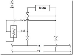
Such complexes are regulated by automatic temperature controller, and the connection occurs in the same way as in closed systems. There are several schemes for such hot water supply connection and each has its own characteristics.
- Typical connection using a thermostat. In such a scheme hot water will mix in the depths of the thermoregulatory device. In this case, the DHW circulation line will be mounted behind the drainage point and behind the throttle washer.
- Combined connection of hot water supply with water supply from the return line. A very convenient scheme for reducing fluctuations in water flow and pressure levels in the pipeline. The heating device is mounted into the system in a sequential manner.
- Combined connection of hot water supply with water supply from the supply line. They are used if the water source has low power, and for a boiler room or station it is necessary high blood pressure, however, the temperature in the pipeline is stable. This is a very economical way.