Variable electric current- current with direction and strength changing over time. Those currents that change only in magnitude are called pulsating. In industry and everyday life, variable is most often used
Conversion to AC electrical can be done as follows. Let us place a coil of wire in a uniform constant magnetic field. With uniform rotation of this coil around the axis, it will continuously change both in magnitude and direction. As a result, a variable in direction and magnitude is formed in the coil. If such a coil is connected to an external circuit, then in it we will obtain an alternating electric current.
When the plane of the rotating coil becomes perpendicular to the lines of force of a given magnetic field, passing through it magnetic flux- the largest (Φ = Φmax), but its rate of change is zero (ΔΦ/Δt = 0), since, passing through this position, the coil conductors slide along the field lines without crossing them. This means that the induced emf generated in the coil will become zero (E = 0).
When the plane of the coil is parallel to the field lines, the flux penetrating it is zero (Φ = 0), and its rate of change in this position is greatest ((ΔΦ/Δt)max), since the conductors of the coil move perpendicular to the field lines.
The emf arising in this case in the turn has the greatest value (E = Emax). With further rotation of the coil, the rate of change of the flow penetrating the coil will increase; This means that the EMF in absolute value will increase from 0 to Emax. Thus, the level of induced emf in a rotating coil changes from -Emax to +Emax during one revolution.
Let's open the coil of wire and connect it to the oscilloscope. When the coil rotates in a magnetic field, the oscilloscope will record all changes in current, by which it will be possible to judge the change electromotive force in a turn during one revolution.
The current arising in the coil when it is uniformly circulated in a uniform magnetic field, as the oscillogram shows, changes sinusoidally. This current is called alternating sinusoidal.
The period of time during which the electromotive force performs one oscillation is called the period AC.
The letter designation of the oscillation period is T. The number of oscillations in 1 second is the current frequency, which is designated by the letter f. Its unit of measurement is hertz (Hz):
f = 1/T, or T = 1/f.
If we denote the value of the EMF at some arbitrary moment in time by e (its instantaneous value), and the largest value (amplitude) by Emax, then the law expressing the dependence of e on time, in the case of a sinusoidal current, can be expressed as the following expression:
e = Emax˖sin (2/T)t.
In most countries, alternating electric current with a frequency of 50 Hz and a period of 0.02 seconds is used in industry and in everyday life.
The production of alternating electric current from mechanical energy is carried out using special machines called generators. The principle of their operation is based on the law of electromagnetic induction. The most simple circuit The generator can be represented in the form of a frame rotating around an axis in the magnetic field of an electromagnet or When the frame rotates, an alternating electromotive force is generated in it. By connecting the frame to an external circuit, we obtain an alternating electric current. An alternating current generator with a fixed magnetic system and rotating coils is built quite rarely.
In almost all such generators, the winding (armature) is installed stationary, and the magnetic system (inductor) rotates. The immovable part of the generator is called the stator, and the moving part is the rotor.
The concept of alternating electric current is given in a general education physics textbook educational institution- schools. Alternating electric current has the form of a harmonic sinusoidal signal, the main characteristics of which are the effective voltage and frequency.
Frequency is the number of complete changes in the polarity of an alternating electric current in one second. This means that the current in a regular household outlet with a frequency of 50 Hertz changes its direction from positive to negative and back exactly fifty times in one second. One complete change in the direction (polarity) of the electric current from a positive value to a negative value and again to a positive value is called the period of oscillation of the electric current. During the period T alternating electric current changes its direction twice.
An oscilloscope is usually used to visually observe the sinusoidal waveform of alternating current. To prevent electric shock and protect the oscilloscope from mains voltage at the input, isolation transformers are used. To measure a period, it makes no difference which equivalent (equal amplitude) points to measure it at. You can use the maximum positive or negative vertices, or you can use the zero value. This is explained in the figure.

From a physics textbook we know that alternating electric current is generated using an electrical machine - a generator. The simplest model of a generator is a magnetic frame rotating in the magnetic field of a permanent magnet.
Let's imagine a rectangular wire frame with several turns, uniformly rotating in a uniform magnetic field. The emf arising in this frame. induction changes according to a sinusoidal law. Oscillation period T alternating electric current is one full revolution of the magnetic frame around its axis. 
One of the important characteristics of electric current are two values of alternating electric current - the maximum value and the average value.
The maximum value of the electric current voltage Umax is the voltage value corresponding to the maximum value of the sinusoid.
Average value of electric current voltage Usr- this is a voltage value equal to 0.636 of the maximum. Mathematically it looks like this: U av = 2 * U max / π = 0.636 U max
The maximum voltage sine wave can be monitored on the oscilloscope screen. You can understand what the average value of alternating electrical voltage is by conducting an experiment using the figure and description below. 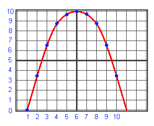
Using an oscilloscope, connect a sinusoidal voltage to its input. Use the vertical sweep offset knob to move the sweep “zero” to the lowest line of the oscilloscope screen scale. Stretch and shift the horizontal scan so that one half-wave of sinusoidal voltage fits into ten (five) cells of the oscilloscope screen. Using the vertical scan (gain) knob, stretch the scan so that the maximum amplitude of the half-wave fits exactly ten (five) cells on the oscilloscope screen. Determine the amplitude of the sinusoid in ten sections. Sum up all ten values and divide by ten - find his “average score”. As a result, you will get a voltage value approximately equal to 6.36 of its maximum value - 10.
Measuring instruments - voltmeters, gauges, multimeters for measuring alternating voltage have a rectifier and a smoothing capacitor in their circuit. This chain “rounds” the multiplier of the difference between the maximum and measured voltage to the number 0.7. Therefore, if you observe a voltage sinusoid with an amplitude of 10 volts on the oscilloscope screen, then the voltmeter (tseshka, multimeter) will show not 10, but about 7 volts. Do you think that your home outlet has 220 volts? It is true, but not entirely true! 220 volts is the average voltage of a household outlet, averaged measuring instrument- voltmeter. The maximum voltage follows from the formula: U max = U meas / 0.7 = 220 / 0.7 = 314.3 volts
That is why, when you are “shocked” by a current from a 220-volt electrical outlet, know that this is your illusion. In fact, you are shaking at about 315 volts.
Three phase current
 Along with simple sinusoidal alternating current, so-called three-phase current is widely used in technology. Moreover, three-phase electric current is the main type of energy used throughout the world. Three-phase current has gained popularity due to its less costly transmission of energy over long distances. If ordinary (single-phase) electric current requires two wires, then three-phase current, which has three times the energy, requires only three wires. You will learn the physical meaning later in this article.
Imagine if not one, but three identical frames rotate around a common axis, the planes of which are rotated 120 degrees relative to each other. Then the sinusoidal emfs arising in them. will also be out of phase by 120 degrees (see figure). 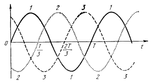
Such three coordinated alternating currents are called three-phase current. A simplified arrangement of wire windings in a three-phase current generator is illustrated in the figure. 
The connection of the generator windings along three independent lines is shown in the figure below. 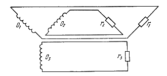
This connection with six wires is quite cumbersome. Since for phenomena in electrical circuits Only potential differences are important, then one conductor can be used for two phases at once, without reducing the load capacity for each phase. In other words, in the case of connecting the generator windings in a "star" configuration using a "zero", the energy transfer from three sources is carried out over four wires (see figure), in which one is common - the neutral wire. 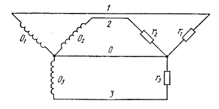
Three wires can transmit energy from three (virtually independent) sources of electric current connected by a “triangle” at once. 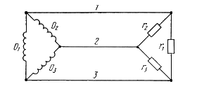
In industrial generators and converter transformers, a phase-to-phase voltage of 220 volts is usually connected using a delta connection. In this case, there is no “neutral” wire.
"Star" is used to transmit network voltage using "zero". In this case, a voltage of 220 volts is applied in the phase relative to “zero”. The phase-to-phase voltage is 380 volts.
A frequent occurrence during the times of “brazenly stealing democracy” was the burning of household equipment in the apartments of respectable citizens, when, due to weak wiring, the common “zero” burned out, then depending on how much household appliances turned on in apartments, TVs and refrigerators were on in those who turned them on the least. This is caused by the phenomenon of “phase imbalance”, which occurs when the zero is broken. Instead of 220 volts, an interphase voltage of 380 volts rushed into the socket of respectable citizens. Until now, in many communal apartments and buildings resembling housing in our Russian cities and towns, this phenomenon has not been completely eradicated.
An alternating current is a current whose change in magnitude and direction is repeated periodically at equal intervals of time T.
In the field of production, transmission and distribution electrical energy alternating current has two main advantages compared to direct current:
1) the ability (using transformers) to simply and economically increase and decrease voltage, this is crucial for transmitting energy over long distances.
2) greater simplicity of electric motor devices, and therefore their lower cost.
The value of a variable quantity (current, voltage, emf) at any time t is called instantaneous value and is denoted by lowercase letters (current i, voltage u, emf - e).
The largest of the instantaneous values of periodically changing currents, voltages or emf is called maximum or amplitude values and are designated by capital letters with the index “m” (I m, U m).
The shortest period of time after which the instantaneous values of a variable quantity (current, voltage, emf) are repeated in the same sequence is called period T, and the totality of changes occurring during the period is cycle.
The reciprocal of the period is called frequency and is denoted by the letter f.
Those. frequency – the number of periods per 1 second.
Frequency unit 1/sec - called hertz (Hz). Larger units of frequency are kilohertz (kHz) and megahertz (MHz).
Obtaining alternating sinusoidal current.
In technology, alternating currents and voltages are sought to be obtained according to the simplest periodic law - sinusoidal. Because a sinusoid is the only periodic function that has a derivative similar to itself, as a result of which the shape of the voltage and current curves in all links of the electrical circuit is the same, which greatly simplifies the calculations.
To obtain industrial frequency currents, use alternators whose operation is based on the law of electromagnetic induction, according to which, when a closed circuit moves in a magnetic field, a current arises in it.
Circuit diagram of a simple alternator
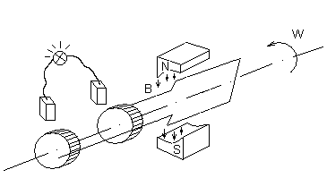
High-power alternating current generators, designed for voltages of 3–15 kV, are made with a stationary winding on the machine stator and a rotating electromagnet-rotor. With this design, it is easier to reliably insulate the wires of the fixed winding and it is easier to divert the current to the external circuit.
One revolution of the rotor of a two-pole generator corresponds to one period of alternating EMF induced on its winding.
If the rotor makes n revolutions per minute, then the frequency of the induced emf
 .
.
Because in this case the angular velocity of the generator  , then between it and the frequency induced by the EMF there is a relationship
  .
.
Phase. Phase shift.

Let us assume that the generator has two identical turns at the armature, shifted in space. When the armature rotates, EMFs of the same frequency and with the same amplitudes are induced in the turns, because the coils rotate at the same speed in the same magnetic field. But due to the shift of turns in space, the EMF does not reach amplitude signs simultaneously.
If at the moment the time count begins (t=0) turn 1 is located at an angle relative to the neutral plane  , and turn 2 is at an angle
  . Then the EMF induced in the first turn:
and in the second:
At the time of countdown:
Electrical angles  And
And  the determining values of the emf at the initial moment of time are called initial phases.
The difference in the initial phases of two sinusoidal quantities of the same frequency is called phase angle .
![]()
The quantity for which zero values (after which it takes on positive values) or positive amplitude values is achieved earlier than the other is considered advanced in phase, and the one for which the same values are achieved later - lagging in phase.
If two sinusoidal quantities simultaneously reach their amplitude and zero values, then the quantities are said to be in phase
. If the phase shift angle of sinusoidal quantities is 180 0  , then they are said to change in antiphase.
Electric current- movement of charged particles along a conductor in a certain direction. More precisely, this is a value that shows how many charged particles passed through the conductor per unit of time. If in one second a number of charged particles the size of one coulomb passed through the cross-section of a conductor, then a current of one ampere (current designation in accordance with the international SI system) flows through this conductor. The amount of electric current (number of amperes) is called current strength. Depending on the change in value over time, current can be constant or variable.
D.C is an electric current that does not change its direction over time. AC- over time, in a certain pattern, changes both its magnitude and direction. Moreover, these changes are repeated at certain intervals - that is, they are periodic.
Alternating and direct current in electrical installations
For three phase electrical network characteristic AC. The flow of alternating current through conductors is determined by the presence of a source of alternating electromotive force (EMF), which changes its value, both in magnitude and in direction. In this case, the change in the magnitude and direction of the EMF is carried out according to the sine law, that is, the graph of changes in alternating current over time is a sinusoid. The source of sinusoidal EMF is an alternating current generator.
Almost all electrical equipment of electrical installations and industrial enterprises is powered from an alternating current network, since this is the most appropriate and has many advantages. But there is also some equipment that operates from a direct current network (or some of its parts): synchronous motor, electromagnetic, DC motor and others. In order to convert alternating current into D.C.(necessary to power the above electrical equipment) use rectifiers.
In addition, direct current is used to transmit large amounts of electrical energy through high-voltage lines. In this case, when transmitting electrical energy over long distances, electrical losses are significantly less than during the same transmission using alternating current.
>> Alternating electric current
§ 31 ALTERNATING ELECTRIC CURRENT
Free electromagnetic oscillations in the circuit quickly fade, and therefore they are practically not used. On the contrary, undamped forced oscillations are of great practical importance.
AC in the lighting network of an apartment, used in factories and factories, etc., is nothing more than forced electromagnetic oscillations. Current and voltage change over time according to a harmonic law.
Voltage fluctuations are easy to detect using an oscilloscope. If voltage from the mains is applied to the vertical deflection plates of the oscilloscope, the time base on the screen will be a sinusoid (Fig. 4.8). Knowing the speed of the beam moving across the screen in the horizontal direction (it is determined by the frequency of the sawtooth voltage), we can calculate the oscillation frequency. The frequency of alternating current is the number of oscillations in 1 s.
Standard frequency industrial alternating current is 50 Hz. This means that over the course of 1 s, the current flows 50 times in one direction and 50 times in the opposite direction. A frequency of 50 Hz is accepted for industrial current in many countries around the world. In the USA the adopted frequency is 60 Hz.
If the voltage at the ends of the circuit changes according to a harmonic law, then the electric field strength inside the conductors will also change harmoniously. These harmonic changes in field strength, in turn, cause harmonic oscillations in the speed of the ordered movement of charged particles and, therefore, harmonic oscillations in the current strength.
But when the voltage changes at the ends of the circuit, the electric field does not change instantly throughout the circuit. Changes in the field propagate, although at a very high, but not at an infinitely high speed.
However, if the propagation time of field changes in the circuit is much less than the period of voltage oscillations, we can assume that the electric field in the entire circuit immediately changes when the voltage at the ends of the circuit changes. In this case, the current strength at a given time will have almost the same value in all sections of the unbranched circuit.
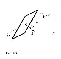
Alternating voltage in the sockets of the lighting network is created by generators at power plants. A wire frame rotating in a constant uniform magnetic field can be considered as the simplest model alternating current generator. The magnetic induction flux Ф, penetrating a wire frame of area S, is proportional to the cosine of the angle a between the normal to the frame and the magnetic induction vector (Fig. 4.9):
With uniform rotation of the frame, angle a increases in direct proportion to time:
where is the angular velocity of rotation of the frame. The magnetic induction flux changes according to the harmonic law:
Here the quantity plays the role of cyclic frequency.
According to the law of electromagnetic induction, the induced emf in the frame is equal to the rate of change of the magnetic induction flux taken with the “-” sign, i.e., the derivative of the magnetic induction flux with respect to time:
If an oscillatory circuit is connected to the frame, then the angular speed of rotation of the frame will determine the frequency of oscillations of the EMF values, voltage in different sections of the circuit and current strength.
We will further study forced electrical oscillations that occur in circuits under the influence of voltage changing with a cyclic frequency ω according to the law of sine or cosine:
u = U m sin t
or
u = U m cos t, (4.14)
where U m is the voltage amplitude, i.e. the maximum absolute value of the voltage.
If the voltage changes with a cyclic frequency, then the current in the circuit will change with the same frequency. But current fluctuations do not necessarily have to be in phase with voltage fluctuations. Therefore, in the general case, the current strength i at any time (instantaneous current value) is determined by the formula
Lesson content lesson notes supporting frame lesson presentation acceleration methods interactive technologies Practice tasks and exercises self-test workshops, trainings, cases, quests homework discussion questions rhetorical questions from students Illustrations audio, video clips and multimedia photographs, pictures, graphics, tables, diagrams, humor, anecdotes, jokes, comics, parables, sayings, crosswords, quotes Add-ons abstracts articles tricks for the curious cribs textbooks basic and additional dictionary of terms other Improving textbooks and lessonscorrecting errors in the textbook updating a fragment in a textbook, elements of innovation in the lesson, replacing outdated knowledge with new ones Only for teachers perfect lessons calendar plan for the year methodological recommendations discussion programs Integrated Lessons