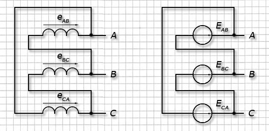
When a 3-phase generator operates, an EMF is created in each of its windings in the form of a sinusoidal oscillation. All vectors are separated by 120° in rotation angle and can be described by the formulas:
e A = E m sinωt, E A = Efe j0° ;
e B =E m sin(ωt-120°), E B =Efe -j120°;
e C =E m sin(ωt-240°)=E m sin(ωt+120°), E C =Efe j120°.
To connect the generator windings to a connected system, one of two schemes is used:
- “star” (Y);
- “triangle” (Δ).
"Star". For the “star” circuit, all outputs of the stator phase windings are connected to a single common point N, called the neutral or zero point. Input (start) of windings of each phase A, B and C connected to the linear terminals of the generator.
"Triangle". For this connection diagram, the output phases are formed:
- "A" connecting the winding output A to the winding input C;
- "IN" connecting the winding output IN to the winding input A;
- "WITH" connecting the winding output WITH to the winding input IN.
Connection points A, B and C used as linear outputs for the generator.
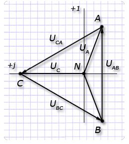
Vector diagrams. For a working generator, the windings of which are connected in a star configuration, the voltage vector diagram has the shape of an equilateral triangle with the center at the origin and located symmetrically relative to the ordinate axis.
 Its sides are represented by vectors of linear stresses with the direction of rotation opposite to the clockwise direction. Vector phase voltages connect the center of the triangle with the vertices in the direction from the origin.
The term phase voltage refers to the potential difference between the common terminal N and the linear one A, B or WITH and mark: U A, U B, U C. The voltages in the generator phases are equal to the EMF of the windings: E A =U A, E B =U B, E C =U C.
The line voltage of the generator is measured between any two of its terminals and is designated by the name of the selected phases: U AB, U BC, U CA. The magnitude of the line voltage vector is determined by the geometric difference between the vectors of the corresponding phases:
U AB =U A -U B;
U BC =U B -U C;
U CA =U C -U A.
For a generator with windings connected in a “triangle” pattern, the voltage vector diagram also has the shape of an equilateral triangle, but it is rotated 30° relative to the coordinate center in the direction of clockwise movement.
 The ratios of linear and phase voltages for a generator assembled according to a “delta” circuit remain the same as for a generator operating according to a “star” circuit.
Parameter calculations three-phase networks carried out using mathematical methods (for example, the complex method) and methods of geometric addition.
To do this, select one of the vectors as the initial one and orient it in the complex plane, taking into account the direction and magnitude. The remaining vectors are completed according to the angles of their phase shift relative to the selected initial vector, taking into account their values.
It is easier to start normal calculations for a star connection circuit by determining the phase vector voltage A, which in this system leaves the origin of the complex plane in the direction to the north. Expressions of phase voltages in complex form for such a calculation are described by the formulas:
U A =Ufe j0°;
U B =Ufe -j120°;
U C =Ufe j120°.
Formulas for linear vectors have the following form:
U AB =Ule j30°;
U BC =Ule -j90°;
U SA = Ule j150° .
For “triangle” circuits, the linear voltage vector is taken as the initial reference U AB. Formulas for calculating phase voltage vectors take the following expressions:
U A =Ufe -j30°;
U B =Ufe -j150°;
U C =Ufe j90°.
Linear voltage vectors are described by the formulas:
U AB = Ule j0° ;
U BC =Ule -j120°;
U SA = Ule j120° .
Having carried out geometric calculations, it is not difficult to determine the linear magnitude of the vector from the phase value:
U l =2U f cos30°=2U f √3/2=U f √3.
Important! The “triangle” winding connection diagram for a generator is practically not suitable for real use, so it is prohibited to use it.
In the phases of the “triangle” circuit, a common circuit is formed, in which a total EMF arises Σe=e AB +e BC +e CA. The values of impedance in the windings are small and even the value of the total EMF is small Σe>0 causes equalizing currents in the “triangle” mains, which are comparable to the rated current value in the generator. This creates large energy losses and significantly reduces the generator efficiency.
Power engineers have a definition of the rated voltage for a 3-phase system. They are called linear voltages, which are expressed in kilovolts (kV, kV). They are represented by values of 0.4; 1.1; 3.5; 6.3; 10.5; 22; 35; 63; 110; 220; 330; 500; 750.
For electricity consumers, the nominal value of 3-phase voltage can be indicated by the ratio of linear and phase voltages U L /U F. For a 0.4 kV power network it will look like: 380/220 volts.
To reduce the number of wires between the generator and the consumer, the phase windings must be connected to each other in a certain way, both in the generator and at the consumer. The generator windings are designated: U1 – U2,
V1 – V2, W1 – W2 (phases A, B, C). Index 1 indicates the beginning of the winding, index 2 indicates the end.
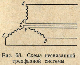
Generator winding connections
In Fig. Figure 68 shows a diagram of a generator that has three independent, mutually isolated single-phase circuits. E.m.f. in these circuits are identical, have the same amplitudes and are shifted in phase by 1/3 of the period. To each pair of generator stator winding terminals, you can connect wires that supply current to the load. It is more profitable to combine these three phases into one common three-phase system. To do this, the generator windings are connected to each other by a star or triangle.
When connecting the generator windings with a star (Fig. 69), the ends of all three phases X, Y and Z (or the beginnings of A, B and C) are connected to each other, and wires are brought out from the beginnings (or ends), discharging energy into the network. The three wires obtained in this way are called linear, and the voltages between any two linear wires are called linear voltages Ul. From the common point of connection of the ends (or beginnings) of the three phases (from the zero point of the star), a fourth wire, called neutral, can be drawn. The voltage between any of the three linear wires and the neutral wire is equal to the voltage between the beginning and end of one phase, i.e., the phase voltage Uph.
Typically, all phases of the generator winding are identical so that the effective values of e. d.s. in phases are equal, i.e. EA = EB = EC. If a load is connected to the circuit of each phase of the generator, then currents will flow through these circuits. In the case of the same value and nature of the resistance of all three phases of the receiver, i.e., a symmetrical (uniform) load, the currents in the phases will be equal in strength and shifted in phase relative to their phase voltages by the same angle φ. Both the maximum and effective values of phase voltages with a uniform load are equal, i.e. UA = UB = Uc. These voltages are 120° out of phase, as shown in the phasor diagram (Fig. 70).
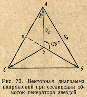
The voltage between any points of the circuit (see Fig. 69) corresponds to the vectors (see Fig. 70) between the same points. So, for example, the voltage between points A and O of the circuit (phase voltage UA) is represented by the vector of the AO diagram, and the voltage between the linear wires A and B of the circuit is represented by the vector of the linear voltage of the AB diagram. Using a vector diagram, it is easy to establish the relationship between linear and phase voltages. From triangle AOa we can write the following relation:
i.e. when connecting the generator windings with a star line voltage times more than phase (with uniform load).
From the diagram (see Fig. 69) it is clear that when the generator windings are connected with a star, the current in the linear wire is equal to the current in the generator phase, i.e. Il = Iph.
Based on Kirchhoff’s first law, we can write that the current in the neutral wire is equal to the geometric sum of the currents in the generator phases, i.e.
With a uniform load, the currents in the generator phases are equal in magnitude, but are shifted in phase relative to each other by 1/3 of the period. The geometric sum of the currents of the three phases in this case is zero, i.e. there will be no current in the neutral wire. Therefore, with a symmetrical load, the neutral wire may be absent. Since the current in the neutral wire arises only due to load asymmetry, and usually this asymmetry is small, in most cases the neutral wire has a smaller cross-section than linear ones.
Star connection
If the phase windings of a generator or consumer are connected so that the ends of the windings are connected to one common point, and the beginnings of the windings are connected to the linear wires, then such a connection is called a star connection and is indicated by the symbol Y. In Fig. 1 windings of the generator and consumer are connected by a star. The points at which the ends of the phase windings of the generator or consumer are connected are called the zero points of the generator (0) and consumer (0’, respectively). Both points 0 and 0' are connected by a wire called the neutral wire. The remaining three wires of the three-phase system, going from the generator to the consumer, are called linear wires. Thus, the generator is connected to the consumer by four wires. Therefore this system is called four wire system three-phase current.
Comparing the unconnected and four-wire three-phase current systems, we see that in the first case, the role of the return wire is performed by three wires of the system, and in the second - one neutral wire. A current flows through the neutral wire equal to the geometric sum of the currents:
IA, IB and IC, i.e. Ī0= ĪA + ĪB + ĪC.
The voltages measured between the beginnings of the phases of the generator (or consumer) and the zero point (or neutral wire) are called phase voltages and are designated UA, UB and UC, or in general Uph. The emf values are often specified. generator phase windings. They are designated EA, EB and EC, or Eph. If we neglect the resistance of the generator windings, we can write:
EA= UA, EB= UB, EC= UC.
Voltages measured between the beginnings of two phases: A and B, B and C, C and A - the generator or consumer, are called linear voltages and are designated UAB, UBC, UCA, or in general form Uл. In Fig. 1, the arrows show the selected positive direction of the current, which in the linear wires is taken from the generator to the consumer, and in the neutral wire - from the consumer to the generator.
If you connect the voltmeter clamps to points A and B, it will show the linear voltage UAB. Since the positive directions of the phase voltages UA, UB and UC are selected from the beginnings of the phase windings to their ends, the linear voltage vector UAB will be equal to the geometric difference of the phase voltage vectors UA and UB:
ŪAB=ŪA- ŪB.
Similarly we can write:
ŪВС=ŪВ- ŪС;
ŪCA=ŪC- ŪA.
Otherwise, we can say that the instantaneous value of the line voltage is equal to the difference in the instantaneous values of the corresponding phase voltages. In Fig. 2 subtraction of vectors is replaced by addition of vectors:
UA and - UB; UВ and - UС; UC and - UA.
From the vector diagram it can be seen that the linear voltage vectors form a closed triangle.
Relationship between linear and phase voltages:
UBC=2UBcos30o, since cos30o=√3/2, then UBC=√3UB,
or in general form Ul=√3Uф.
Therefore, when connected by a star, the line voltage is √3 times the phase voltage.
The current flowing through the phase winding of a generator or consumer is called phase current and is generally designated Iph. The current flowing through a linear wire is called linear current and is generally denoted Il. In Fig. 1 it can be seen that when connected by a star, the linear current is equal to the phase current, i.e.
Il=Iph.
Let's consider the case when the load in the consumer phases is the same both in magnitude and in nature. Such a load is called uniform, or symmetrical. This condition is expressed by the equality
z1= z2= z3.
The load will not be uniform if, for example, z1= r1=0.5 ohm; z2=ωL2=0.5 ohm and z3=1/ωC3=0.5 ohm, since only one condition is met here - the resistance of the consumer phases is equal in value, while the nature of the resistance is different (r1 - active resistance, ωL2 - inductive resistance , 1/ωC3 - capacitance).
With symmetrical load
IА=UA/zА; IВ=UВ/zВ; IС=UC/zС; IA=IB=IC.
Phase power factors due to the equality of resistances and the same nature of their nature will be the same:
cosφ1=rA/zA; cosφ2=rB/zB; cosφ3=rC/zC; cosφ1=cosφ2=cosφ3.
The geometric sum of the currents of all three phases must flow in the neutral wire. If we look at the curves of current changes under a symmetrical load of a three-phase system, we will see that the maximum values for all three current sinusoids are the same. Since with a symmetrical load the sum of the instantaneous current values of the three-phase system is zero, therefore, the current in the neutral wire will be zero.
Discarding the neutral wire in a four-wire system, we move on to a three-wire, three-phase current system. If there is a symmetrical load, such as three phase motors AC, three-phase current, three-phase furnaces, three-phase transformers, etc., then only three wires are connected to such a load. Consumers connected by a star with an asymmetrical phase load require a neutral wire.
With a symmetrical load, the phase voltages of the individual phases are equal to each other. At asymmetrical load In a three-phase system, the symmetry of currents and voltages is broken. However, in four-wire circuits, slight asymmetry of phase voltages is often neglected. In these cases, there is a relationship between linear and phase voltages
Ul=√3Uф.
Connection of three-phase generator windings
2. Methods for connecting the windings of three-phase generators
In the windings of a three-phase generator, sinusoidal EMFs are induced, shifted in phase by 1200:
,
,
,
The phase windings of the generator can be connected to each other according to two different circuits: star () and triangle ().
When connected in a star, the ends of the phase windings (phases) of the generator are connected to a common point N, which is called zero or neutral, and the beginnings of the windings serve as linear outputs of the generator A, IN, WITH(Fig. 88).
The vector diagram of the voltage of a three-phase generator when its phase windings are connected in a star is shown in Fig. 89a, b.
In a three-phase generator, phase and linear voltages are distinguished. Phase voltages are called voltages between the beginnings and ends of phase windings or between one of the linear terminals A, B, C and zero output N. Phase voltages are equal to phase EMF: U A= E A, U B= E IN, U C= E WITH(index N at phase voltages it drops, since φN= 0). Linear voltages are called voltages between two linear terminals A, B, C. Line voltages are equal to the vector difference of two phase voltages: U AB = U A-U IN; U BC = U IN-U WITH; U CA = U WITH-U A.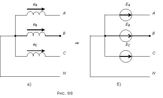
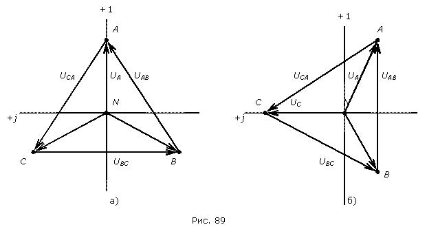
When calculating three-phase circuits using the complex method, the phase and linear voltages of the generator are represented in a complex form, while one of the system vectors is taken as the initial one and combined with the real axis, and the remaining vectors receive the initial phases according to their shift angles with respect to the initial vector. In Fig. 89a shows a variant of representing the voltages of a three-phase generator in complex form, when the phase voltage of the phase is taken as the initial vector A. In this case, the phase voltages of the generator in complex form will take the form: , ![]() ,
, ![]() , linear voltages:
, linear voltages: ![]() ,
, ![]() ,
, ![]() .
.
In Fig. Figure 89b shows another version of representing the voltages of a three-phase generator in complex form, when the linear voltage is taken as the initial vector U AB. In this case, the phase voltages of the generator in complex form will take the form: ![]() ,
, ![]() ,
, ![]() , linear voltages:
, linear voltages: ![]() ,
, ![]() ,
, ![]() .
.
From the geometry of Fig. 5 we obtain the relationship between the modules of linear and phase voltages: UL= 2UФ cos 300 =2 UФ=UФ.
The windings of a three-phase generator can theoretically be connected in a delta circuit. In such a circuit, the end of each previous phase is connected to the beginning of the next one, and the connection points serve as linear terminals of the generator (Fig. 90). 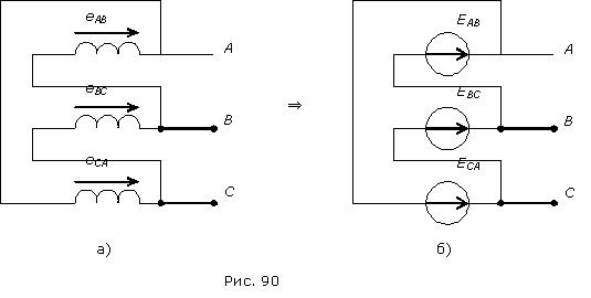
When the phases are connected in a triangle, the sum of the phase EMFs acts in its circuit: = eAB + eBC + eCA. In real three-phase generators it is technically impossible to ensure that the total EMF is equal to zero. Since the own resistance of the generator windings is small, even a small total EMF 0 can cause an equalizing current in the triangle circuit, commensurate with the rated current of the generator, which would lead to additional energy losses and a decrease in the efficiency of the generator. For this reason, the windings of three-phase generators must not be connected in a delta circuit.
The rated voltage in a three-phase system is called line voltage. The rated voltage is usually expressed in kilovolts (kV). The scale of nominal three-phase voltages used in practice is: 0.4; 1.1; 3.5; 6.3; 10.5; 22; 35; 63; 110; 220; 330; 500; 750. At the consumer level, nominal three phase voltage can be specified as a relation U L ⁄ U F, for example: U L ⁄ UФ = 380 ⁄ 220 V.
When connecting the windings in a star, the ends of the windings X, Y, Z are connected to one point, called the zero point or neutral of the generator (Fig. 7-5). In a four-wire system, the neutral or neutral wire is connected to the neutral. Three linear wires are connected to the beginning of the generator windings.
The voltages between the beginnings and ends of the phases, or, what is the same, the voltages between each of the linear wires and the neutral wire are called phase voltages and are designated or in general form
Neglecting the voltage drop in the generator windings, we can consider the phase voltages equal to the corresponding e. d.s. induced in the generator windings.
The voltages between the beginnings of the windings, or, what is the same, between linear wires, are called linear voltages and are designated or in general form
Let us establish the relationship between linear and phase voltages when connecting the generator windings with a star.
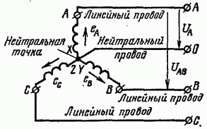
Rice. 7-5. Star connection diagram of generator windings.
Rice. 7-6. Vector diagram of three-phase circuit voltages.
Since the end of the first phase X is connected not to the beginning of the second phase, but to its end Y, which is similar to the counter connection of two sources of e. d.s. at constant current, then the instantaneous value of the linear voltage between wires A and B will be equal to the difference in the corresponding phase voltages, i.e.
similarly instantaneous values of other linear voltages
Thus, the instantaneous value of the line voltage is equal to the algebraic difference of the instantaneous values of the corresponding phase voltages.
Since they change according to a sinusoidal law and have the same frequency, the linear voltages will also change sinusoidally, and the effective values of the linear voltages can be determined from the vector diagram (Fig. 7-6):
From the above it follows that the linear voltage vector is equal to the difference between the vectors of the corresponding phase voltages.
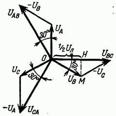
Phase voltages are shifted from each other by 120°. To determine the linear voltage vector, you need to geometrically subtract the vector from the voltage vector, or, what is the same, add a vector - equal in magnitude and opposite in sign.
Similarly, we obtain the linear voltage vector as the difference between the voltage vectors and the linear voltage vector as the difference between the vectors and OA.
By lowering the perpendicular from the end of an arbitrary phase voltage vector, for example, to the linear voltage vector, we obtain a right triangle OHM, from which it follows that
![]()
![]()

Rice. 7-7. Vector diagram of voltages when connecting the generator windings with a star.
From the vector diagram (Fig. 7-6) and the last formula it follows that the effective value of the linear voltage is several times greater than the effective value of the phase voltage and that the linear voltage is 30° ahead of the phase voltage; by the same angle the linear voltage leads the phase voltage and voltage-phase voltage
Adjacent, linear voltages are shifted relative to each other at the same angles (120°) as adjacent phase voltages. The star of the linear voltage vectors is rotated in the positive direction relative to the star of the phase voltage vectors at an angle of 30°.
It is necessary to pay attention to the fact that the obtained relationships between linear and phase voltages take place only with a symmetrical voltage system.
Since the linear voltage vectors are defined as the differences between the phase voltage vectors, by connecting the ends of the phase voltage vectors forming a star, we obtain a triangle of linear voltage vectors (Fig. 7-7).
Example 7-1. Determine the linear voltage of the generator if its phase voltage is 127 and 220 V.
If the phase voltage is 220 V, then
§ 63. Generator winding connections
In Fig. Figure 68 shows a diagram of a generator that has three independent, mutually isolated single-phase circuits. E.m.f. in these circuits are identical, have the same amplitudes and are shifted in phase by 1/3 of the period. To each pair of generator stator winding terminals, you can connect wires that supply current to the load. It is more profitable to combine these three phases into one common three-phase system. To do this, the generator windings are connected to each other by a star or triangle.
star(Fig. 69) ends of all three phases X, Y And Z(or started A, IN And WITH) are connected to each other, and from the beginnings (or ends) wires are brought out, discharging energy into the network. The three wires thus obtained are called linear, and the voltage between any two linear wires is linear voltage U l. From the common point of connection of the ends (or beginnings) of the three phases (from the star zero point), a fourth wire, called zero. The voltage between any of the three linear wires and the neutral wire is equal to the voltage between the beginning and end of one phase, i.e. phase voltage U f.
Typically, all phases of the generator winding are identical so that the effective values of e. d.s. in phases are equal, i.e. E A = E B = E C. If a load is connected to the circuit of each phase of the generator, then currents will flow through these circuits. In the case of the same value and nature of the resistance of all three phases of the receiver, i.e., a symmetrical (uniform) load, the currents in the phases will be equal in strength and shifted in phase relative to their phase voltages by the same angle φ. Both the maximum and effective values of phase voltages with a uniform load are equal, i.e. U A = U B = U c. These voltages are 120° out of phase, as shown in the phasor diagram (Fig. 70).
The voltage between any points of the circuit (see Fig. 69) corresponds to the vectors (see Fig. 70) between the same points. So, for example, the voltage between points A And O circuits (phase voltage U A) is represented by the vector JSC diagrams, and the voltage between the linear wires A And B circuit - linear voltage vector AB diagrams. Using a vector diagram, it is easy to establish the relationship between linear and phase voltages. From a triangle AOa we can write the following relation:
that is, when the generator windings are connected with a star, the linear voltage is several times greater than the phase voltage (with a uniform load).
From the diagram (see Fig. 69) it is clear that when the generator windings are connected with a star, the current in the linear wire is equal to the current in the generator phase, i.e. I l = I f.
Based on Kirchhoff’s first law, we can write that the current in the neutral wire is equal to the geometric sum of the currents in the generator phases, i.e.
With a uniform load, the currents in the generator phases are equal in magnitude, but are shifted in phase relative to each other by 1/3 of the period. The geometric sum of the currents of the three phases in this case is zero, i.e. there will be no current in the neutral wire. Therefore, with a symmetrical load, the neutral wire may be absent. Since the current in the neutral wire arises only due to load asymmetry, and usually this asymmetry is small, in most cases the neutral wire has a smaller cross-section than linear ones.
When connecting the generator windings triangle(Fig. 71) the beginning (or end) of each phase of the generator windings is connected to the end (or beginning) of the winding of another phase. Thus, the three phases of the generator form a closed circuit in which the electric current operates. d.c., equal to the geometric sum e. d.s. induced in the phases of the generator, i.e. ![]() . Since e. d.s. in the phases of the generator are equal and shifted by 1/3 of the period in phase, then their geometric sum is equal to zero, since the vectors of e. d.s. form a closed triangle and, therefore, in the closed loop of a three-phase system connected by a delta, there is no internal current will not arise.
. Since e. d.s. in the phases of the generator are equal and shifted by 1/3 of the period in phase, then their geometric sum is equal to zero, since the vectors of e. d.s. form a closed triangle and, therefore, in the closed loop of a three-phase system connected by a delta, there is no internal current will not arise.
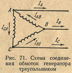
Linear wires, when connected in a triangle, are connected to the connection points of the beginning of one phase and the end of another. The voltage between line wires is equal to the voltage between the beginning and end of one phase. Thus, when the generator windings are connected with a triangle, the linear voltage is equal to the phase voltage, i.e. U l = U f.
With a uniform load, the phases of the generator windings flow equal currents, shifted relative to the phase voltages by equal angles φ, i.e.
I AB = I BC = I CA.
In Fig. 72, and a vector diagram is shown, which shows the vectors of phase voltages and currents.
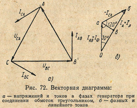
Connection points for phase and linear wires A, IN And WITH are branching points; Line currents are not equal to phase currents. Taking the positive direction of phase and linear currents indicated in Fig. 70, based on Kirchhoff’s first law for instantaneous current values, the following expressions can be written:
Since the currents in the coils are sinusoidal, we replace the algebraic subtraction of the instantaneous current values with the geometric subtraction of vectors depicting their effective values.