Equipped with single-phase electric motors large number low-power refrigeration units used in everyday life (home refrigerators, freezers, household air conditioners, small heat pumps...).
Despite their very widespread use, single-phase motors with auxiliary windings are often undervalued compared to three-phase motors.
The purpose of this section is to study connection rules single-phase electric motors, their repair and maintenance, as well as consideration of the components and elements necessary for their operation (capacitors, starting relays). Of course, we will not study how and why such engines rotate, but we will try to outline all the features of their use as engines for refrigeration compressors.
A) Single-phase motors with auxiliary winding
Such motors, installed in most small compressors, are powered by a voltage of 220 V. They consist of two windings (see Fig. 53.1).
The main winding P, called ________
often the working winding, or in English Run (R), has a thick wire, which remains energized during the entire period of engine operation and passes the rated current of the engine.
The auxiliary winding A, also called the starting winding, or in English S (Start), has a wire of a thinner cross-section, therefore, greater resistance, which makes it easy to distinguish it from the main winding.
The auxiliary or starting winding, as the name suggests, serves to ensure that the engine starts.
Indeed, if you try to start the engine by applying voltage only to the main winding (and not energizing the auxiliary), the motor will hum, but will not start rotating. If you manually turn the shaft at this moment, the motor will start and rotate in the direction in which it was turned manually. Of course, this starting method is not at all suitable for practice, especially if the motor is hidden in a sealed casing.
The starting winding serves precisely to start the engine and provide a starting torque higher than the resistance moment on the motor shaft.
Next we will see that, as a rule, a capacitor is introduced into the circuit in series with the starting winding, providing the necessary phase shift (about 90°) between the current in the main and starting windings. This artificial dephasing is what allows the engine to start.
Attention! All measurements must be carried out with great care and accuracy, especially if the engine model is unfamiliar to you or there is no winding connection diagram.
Accidental mixing of the main and auxiliary windings, as a rule, ends with the motor burning out soon after voltage is applied!
Feel free to repeat the measurements several times and sketch out the motor diagram, providing it with as many notes as possible, this will allow you to avoid many mistakes!
NOTE
If the motor is three-phase, the ohmmeter will show equal resistance values between all three terminals. Thus, it seems that it is difficult to make a mistake when calling this type of engine (by three-phase motors see section 62).
In any case, get in the habit of reading the data sheet on the motor housing, and also think about looking inside the terminal box by removing its cover, as it often provides a diagram of the connection of the motor windings.
Engine check. One of the most difficult issues for a novice repairman is deciding whether, based on the test results, the engine should be considered burnt out. Let us recall the main electrical defects most often found in motors (no matter single-phase or three-phase). Most of these defects are caused by severe overheating of the motor due to excessive current consumption. An increase in current may be the result of electrical (prolonged voltage drop, overvoltage, poor setting of safety devices, poor electrical contact, faulty contactor) or mechanical (seizing due to lack of oil) problems, as well as anomalies in the refrigeration circuit (too high condensing pressure, presence of acids in the circuit...).
One of the windings may be broken. In this case, when measuring its resistance, the ohmmeter will show a very large value instead of the normal resistance. Make sure your ohmmeter is working properly and that its clamps make good contact with the winding terminals. Feel free to check the ohmmeter with a good standard.
Let us recall that the winding of a conventional motor has a maximum resistance of several tens of Ohms for small motors and several tenths of an Ohm for large motors. If the winding is broken, you will need to either replace the motor (or the entire unit) or rewind it (in the case where such a possibility exists, rewinding is more profitable the greater the motor power).
Between two windings there can be short circuit. To perform this test, the connecting wires (and connecting jumpers on a three-phase motor) must be removed.
When you disconnect, never hesitate to first develop a detailed measurement diagram and make as many notes as possible so that in the future you can calmly and without errors put the connecting wires and jumpers back in place.
The ohmmeter should show infinity. However, it shows zero (or very low resistance), which undoubtedly means there is a possibility of a short circuit between the two windings.
This check is less indicative of single phase motor with an auxiliary winding in case the two windings cannot be separated (when the common point C connecting the two windings is inside the motor). Indeed, depending on the exact location of the short circuit, resistance measurements taken between the three terminals (C -> A, C -> P and P -> A) give lower, but rather unrelated values. For example, the resistance between points A and P may not correspond to the sum of resistances C -> A + C -> P.
Just as in the case of broken windings, if there is a short circuit between the windings, it is necessary to either replace or rewind the motor.

The winding can be shorted to ground. The insulation resistance of the new motor (between each winding and ground) must reach 1000 MQ. Over time, this resistance decreases and can drop to 10... 100 MQ. As a rule, it is generally accepted that starting from 1 MQ (1000 kQ), it is necessary to replace the motor, and with an insulation resistance value of 500 kQ and below, operation of the motor is not allowed (remember: 1 MQ = 103 kQ = 10°>Q).
Winding shorted to ground
Resistance approaches zero
If the insulation is broken, measuring the resistance between the winding terminal and the motor housing gives zero resistance (or very low resistance) instead of infinity (see Fig. 53.8). Note that this measurement must be made at each motor terminal using the most accurate ohmmeter available. Before each measurement, make sure that your ohmmeter is in good condition and that its clamps make good contact with the terminal and the metal of the motor housing (if necessary, scrape off the paint on the housing to ensure good contact).
In the example in Fig. 53.8 measurement indicates that the winding can undoubtedly be shorted to the housing.
Rice. 53.8.
However, the contact of the winding with the ground may not be complete. Indeed, the insulation resistance between the windings and the frame can become low enough when the motor is energized to cause the circuit breaker to trip, while remaining high enough to not be detected by a conventional ohmmeter in the absence of voltage.
In this case, it is necessary to use a megger (or similar device), which allows you to monitor the insulation resistance using a constant voltage of 500 V, instead of several volts for a conventional ohmmeter
When rotating the hand-held inductor of the megohmmeter, if the insulation resistance is normal, the arrow of the device should deviate to the left (position 1) and indicate infinity (oo). A weaker deviation, for example at level 10 MQ (item 2), indicates a decrease in the insulation characteristics of the motor, which, although not sufficient to cause the circuit breaker to trip, should nevertheless be noted and corrected , since even minor damage to the insulation, in addition to existing ones, in most cases will sooner or later lead to a complete shutdown of the unit.
Note also that only a megohmmeter can make it possible to perform a quality check of the insulation of two windings between themselves when they cannot be separated (see above the problem of a short circuit between windings in a single-phase motor). In conclusion, we point out that checking a suspicious electric motor must be carried out very strictly.
In any case, it is not enough to just replace the engine, but it is also necessary to find, in addition to this, the root cause of the malfunction (mechanical, electrical or other nature) in order to radically exclude any possibility of its recurrence. In refrigeration compressors, where there is a high likelihood of acid in the working fluid (detected by simple oil analysis), additional precautions will need to be taken after replacing a burnt out motor. You should not neglect the inspection of electrical equipment (if necessary, replacing the contactor and breaker, checking connections and fuses...).
In addition to this, replacing a compressor requires highly qualified personnel and strict adherence rules: draining the refrigerant, if necessary, flushing the circuit afterwards, possibly installing an anti-acid filter on the suction line, replacing the filter drier, searching for leaks, dehydrating the circuit by evacuation, charging the circuit with refrigerant and full control of the operation... Finally, especially if the installation was initially charged with CFC type refrigerant (R12, R502...), maybe it would be possible and advisable to use a compressor replacement to change the type of refrigerant?
B) Capacitors
To start a single-phase motor with an auxiliary winding, it is necessary to ensure a phase shift AC in the auxiliary winding in relation to the main one. To achieve a phase shift and, therefore, provide the required starting torque (remember that the starting torque of the motor must necessarily be greater than the resistance moment on its shaft), capacitors are mainly used, installed in series with the auxiliary winding. From now on, we must remember that if the capacitor capacitance is chosen incorrectly (too small or too large), the achieved phase shift value may not ensure starting of the motor (the motor stalls).
In the electrical equipment of refrigeration units we will deal with two types of capacitors:
Working (running) capacitors (paper) of small capacity (rarely more than 30 microfarads), and of considerable size.
Starting capacitors (electrolytic), on the contrary, have a large capacity (can exceed 100 μF) with relatively small sizes. They should not be constantly energized, otherwise such capacitors will overheat very quickly and may explode. As a rule, it is believed that the time they are energized should not exceed 5 seconds, and the maximum permissible number of starts is no more than 20 per hour.
On the one hand, the size of capacitors depends on their capacitance (the larger the capacitance, the larger the size). The capacitance is indicated on the capacitor body in microfarads (dr, or uF, or MF, or MFD, depending on the designer) with manufacturer tolerance, for example: 15uF±10% (capacitance can range from 13.5 to 16.5 µF) or 88 -108 MFD (capacitance ranges from 88 to 108 µF).
In addition, the size of the capacitor depends on the voltage indicated on it (the higher the voltage, the larger the capacitor). It is useful to remember that the voltage specified by the designer is the maximum voltage that can be applied to the capacitor without fear of destruction. So, if 20 µF/360V is indicated on the capacitor, this means that such a capacitor can be freely used in a network with a voltage of 220 V, but in no case should a voltage of 380 V be supplied to it.
| 53.1. EXERCISE |
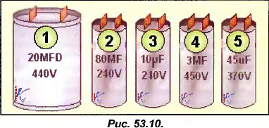
Try for each of the 5 capacitors shown in Fig. 53.10 on the same scale, determine which of them are working (running) and which are starting.
Capacitor No. 1 is the largest in size of all presented, but has a rather low capacitance compared to its size. Apparently this is a working capacitor.
Capacitors No. 3 and No. 4, with the same dimensions, have a very small capacitance (note that capacitor No. 4, intended for use in a network with a supply voltage higher than capacitor No. 3, has a lower capacitance). Therefore, these two capacitors are also working.
Capacitor No. 2 has, in comparison with its size, a very large capacitance, therefore it is a starting capacitor. Capacitor No. 5 has a slightly smaller capacity than No. 2, but it is designed for more high voltage: This is also a starting capacitor.
Checking capacitors. Measurements with an ohmmeter, when they give the results we have just discussed, are excellent evidence of the health of the capacitor. However, they must be complemented by measuring the actual capacitance of the capacitor (we will see how to perform such a measurement shortly).
Now let's study typical capacitor malfunctions (open circuit, short circuit between plates, short circuit to ground, low capacity) and ways to identify them. First of all, it should be noted that swelling of the capacitor housing is completely unacceptable.
There may be a lead break in the capacitor
Then an ohmmeter connected to the terminals and set to the maximum range constantly shows infinity. With such a malfunction, everything happens as if there was no capacitor. However, if the motor is equipped with a capacitor, then it is needed for something. Therefore, we can imagine that the engine will either not work normally or will not start, which will often cause the thermal protection to be triggered (thermal protection relay, circuit breaker...).
There may be a short circuit between the plates inside the capacitor
With such a fault, the ohmmeter will show zero or very low resistance (use a small range). Sometimes the compressor will start (we'll see why later), but in most cases a short circuit in the capacitor will cause the thermal protection to trip.
The plates can be shorted to ground
The capacitor plates, as well as the electric motor windings, are isolated from ground. If the insulation resistance drops sharply (the danger of which occurs when excessive overheating), current leakage causes the installation to be switched off by the circuit breaker.
This malfunction may occur if the capacitor has a metal shell. The resistance measured between one of the terminals and the body in this case tends to 0, instead of being infinite (both terminals need to be checked).
Capacitor capacity may be reduced
In this case, the actual value of the capacitance measured at its ends is lower than the capacitance indicated on the body, taking into account the manufacturer's tolerance.
The measured capacitance would have to be in the range from 90 to 110 µF. Therefore, in fact, the capacitance is too low, which will not provide the required phase shift and starting torque. As a result, the engine may no longer start.
Let us now consider how to measure the actual capacitance of a capacitor using a simple circuit that can be easily implemented at the installation site.
ABOUT
ATTENTION! To eliminate possible hazards, it is necessary to test the capacitor using an ohmmeter before assembling this circuit.
It is enough to connect an externally working capacitor to an alternating current network with a voltage of 220 V and measure the current consumed (of course, in this case, the operating voltage of the capacitor must be at least 220 V).
The circuit must be protected either by a circuit breaker or a fuse with a switch. The measurement should be as short as possible (it is dangerous to keep the starting capacitor energized for a long time).
At 220 V, the actual capacitance of the capacitor (in microfarads) is approximately 14 times the current consumption (in amperes).
For example, you want to check the capacitance of a capacitor (obviously this is a starting capacitor, so the time it remains energized should be very short, see Fig. 53.21). Since it indicates that the operating voltage is 240 V, it can be connected to a 220 V network.
If the capacitance marked on the capacitor is 60 µF ± 10% (that is, 54 to 66 µF), theoretically it should draw a current of: 60 / 14 = 4.3 A.
We will install the machine or fuse, designed for such a current, we connect the transformer clamps and set the measuring range on the ammeter, for example, 10 A. We apply voltage to the capacitor, read the ammeter readings and immediately turn off the power.
WARNING, DANGER! When you measure the capacitance of a starting capacitor, the time it is under voltage should not exceed 5 seconds (practice shows that with little expense in organizing the measurement process, this time is quite enough to complete the measurement).
In our example, the actual capacitance is about 4.1 x 14 = 57 µF, meaning the capacitor is good as its capacitance should be between 54 and 66 µF.
If the measured current were, for example, 3 A, the actual capacitance would be 3 x 14 = 42 µF. This value is outside the tolerance limits, therefore the capacitor would need to be replaced.
B) Start relays
In most cases (but not always), these relays are connected directly to the compressor using two or three (depending on models) sockets that accept the motor winding plugs, preventing possible errors when connecting the relay to the auxiliary and main windings. The top cover of the relay is usually marked with the following symbols:
R / M -> Working (Main) -> Main winding A / S -> Starting (Start) -> Auxiliary winding L Line (Line) -> Supply phase
If the relay is turned upside down, you can clearly hear the sound of the moving contacts sliding freely.
Therefore, when installing such a relay, it is necessary to strictly maintain its spatial orientation so that the inscription “Top” (Top) is on top, since if the relay is upside down, its normally open contact will be constantly closed.
When checking the resistance between the contacts of the current starting relay with an ohmmeter (if it correct location) between sockets A/S and P/M, as well as between sockets L and A/S, there must be an open circuit (resistance equal to co), since when the power is removed the relay contacts are open.
Between the P/M and L sockets, the resistance is close to 0, corresponding to the resistance of the relay coil, which is wound with a thick wire and is designed to pass the starting current.
You can also check the resistance of the relay inverted. In this case, between sockets A/S and L, instead of infinity, there should be a resistance close to zero.
When installing the current relay in an inverted position, its contacts will remain permanently closed, which will not allow the starting winding to be disconnected. As a result, there is a danger of rapid combustion of the electric motor.
Let us now study the operation of the starting current relay in the circuit shown in the absence of voltage.
As soon as voltage is applied to the circuit, current will flow through the thermal protection relay, the main winding and the relay coil. Since contacts A/S and L are open, the starting winding is de-energized and the engine does not start - this causes a sharp increase in current consumption.
An increase in the starting current (approximately five times the nominal value) provides such a voltage drop on the relay coil (between points L and P/M) that becomes sufficient for the core to be drawn into the coil, contacts A/S and L to close and the starting winding to turn out to be under voltage.
Thanks to the impulse received from the starting winding, the engine starts and as its speed increases, the current consumption decreases. At the same time, the voltage on the relay coil drops (between L and R/M). When the motor reaches approximately 80% of the rated speed, the voltage between points L and P/M will become insufficient to hold the core inside the coil, the contact between A/S and L will open and completely turn off the starting winding.
However, with such a circuit, the starting torque on the motor shaft is very insignificant, since it does not have a starting capacitor, which provides a sufficient phase shift between the current in the main and starting windings (remember that the main purpose of the capacitor is to increase the starting torque). Therefore, this circuit is used only in small motors with an insignificant moment of resistance on the shaft.
If we are talking about small refrigeration compressors, in which capillary tubes are necessarily used as an expansion device, ensuring equalization of the pressure in the condenser and the pressure in the evaporator during stops, then in this case the engine starts at the minimum possible moment of resistance on the shaft (see section 51 . "Capillary expansion devices").
If it is necessary to increase the starting torque, it is necessary to install a starting capacitor (Cd) in series with the starting winding. Therefore, current relays are often produced with four sockets, such as in the model presented.
Relays of this type are supplied with a shunt jumper between sockets 1 and 2. If it is necessary to install a starting capacitor, the shunt is removed.
Note that when testing such a relay with an ohmmeter between sockets M and 2, the resistance will be close to zero and equal to the resistance of the relay winding. Between sockets 1 and S, the resistance is equal to infinity (with the relay in normal position) and zero (with the relay turned upside down).
ATTENTION! When replacing a faulty current relay, the new relay must always have the same index as the faulty one.
Indeed, there are dozens of different modifications of current relays, each of which has its own characteristics (closing and opening current, maximum permissible current...). If the newly installed relay has different characteristics from the relay being replaced, then either its contacts will never close or will remain permanently closed.
If the contacts never close, for example because the starting current relay is too high (designed to close at 12 A starting current when in fact the starting current does not exceed 8 A), the auxiliary winding cannot be energized and the engine does not start. It hums and is turned off by a thermal protection relay.
Note that these same symptoms accompany a malfunction such as broken relay contacts
As a last resort, you can test this hypothesis by short-circuiting contacts 1 and S for a few seconds, for example. If the engine starts, this will be evidence of a faulty relay.
If the contact remains constantly closed, for example, due to the low power of the starting current relay (it should open when the current drops to 4 A, and the motor at rated mode consumes 6 A), the starting winding will be energized all the time. Note that the same thing will happen if, due to excessive current, the relay contacts become “welded” or if the relay is mounted upside down*, causing the contacts to remain permanently closed.
The compressor will then consume enormous current and, in the best case, will be turned off by the thermal protection relay (in the worst case, it will burn out). If there is a starting capacitor in the circuit, it will also be energized all the time and will overheat greatly every time you try to start, which will ultimately lead to its destruction.
The normal operation of the starting current relay can be easily checked using transformer clamps installed in the line of the capacitor and the starting winding. If the relay is working normally, then at the moment of startup the current will be maximum, and when the contact opens, the ammeter will show no current.
Finally, to complete our consideration of the starting current relay, we need to dwell on one malfunction that can occur when the condensation pressure increases excessively. Indeed, any increase in condensation pressure, no matter what it is caused by (for example, a condenser is dirty), inevitably leads to an increase in the current consumed by the motor (see section 10. “The influence of the condensation pressure on the current consumed by the compressor electric motor”). This increase can sometimes be sufficient to cause the relay to operate and the contacts to close while the motor is spinning. You can imagine the consequences of such a phenomenon!
* Installing the start relay in a horizontal plane, as a rule, gives the same result and is also incorrect (editor's note).
When the engine power increases (becoming higher than 600 W), the current consumption also increases, and the use of a current starting relay becomes impossible due to the fact that the required diameter of the relay coil increases. The starting voltage relay also has a coil and contacts, but unlike the current relay, the voltage relay coil has a very high resistance (wound with a thin wire with a large number of turns), and its contacts are normally closed. Therefore, the likelihood of confusing these two devices is very small.
presented appearance the most common voltage starting relay, which is a sealed black box. If you test the relay terminals with an ohmmeter, you will find that between terminals 1 and 2 the resistance is 0, and between 1-5 and 2-5 it is the same and amounts to, for example, 8500 Ohms (note that terminals 4 are not included in the circuit and are used only for the convenience of connecting and routing wires on the relay body).
The relay contacts are probably located between terminals 1 and 2, since the resistance between them is zero, but it is impossible to determine which of these terminals one of the coil terminals is connected to, since the measurement result will be the same (see diagram in Fig. 53.29).
If you have a relay circuit, there will be no problems determining the common point. Otherwise, you will need to perform an additional small experiment, that is, apply power first to terminals 1 and 5, and then 2 and 5 (the measured resistance between them was 8500 Ohms, therefore, one of the ends of the coil is connected to either terminal 1 or terminal 2).
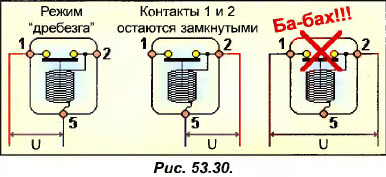
Let’s assume that when voltage is applied to terminals 1-5, the relay will operate in the “bounce” mode (like a buzzer) and you will clearly distinguish between the constant closing and opening of its contact (imagine the consequences of such a mode for the engine). This will be a sign that terminal 2 is common and one of the ends of the coil is connected to it. In case
If you are unsure, you can test yourself by applying power to terminals 5 and 2 (pins 1 and 2
open and will remain open).
ATTENTION! If you apply voltage to terminals 1 and 2 (normally closed contact terminals), you will create a short circuit, which can be very dangerous.
To perform this test, you must use 220V voltage if the relay is designed to fit a 220V motor (we strongly recommend using a fuse in the circuit to protect the circuit from possible wiring errors). However, it may happen that the relay contacts will not open either when power is applied to terminals 1 and 5, or when it is applied to terminals 2 and 5, although the coil will be in good condition (when tested with an ohmmeter, the resistance of 1-5 and 2-5 is equally high) . This may be due to the very principle underlying the operation of the circuit with a voltage relay (we will look at it immediately after this paragraph), which requires an increased voltage relay to operate. To continue the test, you can increase the voltage to 380 V (the relay is not in danger, since it can withstand voltage up to 400 V).
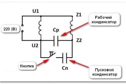
As soon as power is applied to the circuit, current flows through the thermal protection relay and the main winding (C->P). At the same time, it passes through the starting winding (C-»A). normally closed contacts 2-1 and starting capacitor (Cd). All starting conditions are met and the engine begins to rotate.
As the engine gains speed, additional voltage is induced in the starting winding, which is added to the supply voltage.
At the end of the start, the induced voltage becomes maximum and the voltage at the ends of the starting winding can reach 400 V (with a supply voltage of 220 V). The voltage relay coil is designed to open its contacts precisely when the voltage across it exceeds the supply voltage by an amount determined by the engine designer. When the contacts I -2 open, the relay coil remains energized by the voltage induced in the starting winding (this winding, wound on the main winding, is like a secondary winding of the transformer).
During starting, it is very important that the voltage at the relay terminals exactly matches the voltage at the ends of the starting winding. Therefore, the starting capacitor should always be included in the circuit between points I and P, and not between A and 2. Note that when contacts 1-2 are opened, the starting capacitor is completely excluded from the circuit.
There are many different models of voltage relays, differing in their characteristics (closing and opening voltage...).
Therefore, if it is necessary to replace a faulty voltage relay, you need to use a relay of the same model.
If the replacement relay does not fully match the engine, this means that either its contacts will not be closed when starting, or will be permanently closed.
When the relay contacts are open during startup, for example because the relay is too low-power (it operates at 130 V, that is, immediately after voltage is applied and the starting winding is energized only as a secondary winding), the engine will not be able to start, will hum and shut down thermal protection relay (see Fig. 53.33).
Note that the same symptoms will occur if the contact breaks. As a last resort, you can always test this hypothesis by briefly short-circuiting contacts 1 and 2. If the engine starts, then there is no contact.
Triggering using thermistor (TR)
A thermistor, or thermistor (STR * - abbreviation, translated means a positive temperature coefficient, that is, an increase in resistance with increasing temperature) is included in the circuit as shown in Fig. 53.37.
When the motor rotor is stationary, the STR is cold (at ambient temperature) and its resistance is very low (several ohms). As soon as voltage is applied to the motor, the main winding is energized. At the same time, current passes through the low resistance CTP and the starting winding, causing the motor to start. However, the current flowing through the starting winding, passing through the STR, heats it up, which causes a sharp increase in its temperature, and therefore in resistance. After one or two seconds, the temperature of the STR becomes more than 100 ° C, and its resistance easily exceeds 1000 Ohms.
A sharp increase in the resistance of the CTP reduces the current in the starting winding to a few milliamps, which is equivalent to turning off this winding in the same way as a conventional starting relay would do. A weak current, without having any effect on the state of the starting winding, continues to pass through the SCR, remaining quite sufficient to maintain its temperature at the desired level.
This start-up method is used by some developers if the moment of resistance at start-up is very small, for example, in installations with capillary expansion devices (where pressure equalization is inevitable during shutdown).
However, when the compressor has stopped, the duration of the stop must be long enough to not only equalize the pressures, but also, mainly, to cool the CTE (according to calculations, this requires at least 5 minutes).
Any attempt to start the engine with a hot CV (having, therefore, a very high resistance) will not allow the starting winding to start the engine. Such an attempt can result in a significant increase in current and tripping of the thermal protection relay.
Thermistors are ceramic disks or rods, and the main type of malfunction of this type of starting devices is their cracking and destruction of internal contacts, most often caused by attempts to start with hot CSRs, which
inevitably entails an excessive increase in the starting current.
. We have often pointed out the importance of maintaining the identity of models when replacing faulty elements of electrical equipment (thermal protection relays, starting relays...) with new ones, or with those recommended for replacement by the developer. We also recommend that when replacing the compressor, you also change the set of starting devices (relay + capacitor(s)).
* Sometimes the term RTS is used, which means the same as STR (approx. peo.j.
D) Generalization of the most common starting device circuits
In the documentation of various developers there are many schemes with several exotic names, which we will now explain. Taking this opportunity, we will expand our knowledge and see the role of working capacitors.
For a better understanding of further material, let us recall that, unlike starting capacitors, working capacitors are designed to be constantly energized and that the capacitor is included in the circuit in series with the starting winding, allowing an increase in torque per motor wattage.
1) PSC (Permanent Split Capacitor) circuit - the circuit with a permanently connected capacitor is the simplest, since it does not have a start relay.
A capacitor, constantly under voltage (see Fig. 53.40\) must be a working capacitor. Since this type of capacitor quickly increases in size with increasing capacitance, their capacitance is limited to small values (rarely more than 30 μF).
Consequently, the PSC circuit is used, as a rule, in small motors with a low torque on the shaft (small refrigeration compressors for capillary expansion devices that provide pressure equalization during stops, fan motors of small air conditioners).
When voltage is applied to the circuit, the permanently connected con-
the densator (Cp) gives a boost, allowing the engine to start. When the engine is running, the starting winding remains energized along with the capacitor in series, which limits the current and allows for increased torque when the engine is running.
2) Scheme PAGE. previously studied, is also called PTC (Positive Temperature Coefficient) and is used as a relatively simple starting device.
It can be improved by adding a permanently connected capacitor.
When voltage is applied to the circuit (after a stop of at least 5 minutes), the resistance of the thermistor STR is very low and the capacitor Cp, being short-circuited, does not affect the startup process (hence, the resistance moment on the shaft should be insignificant, which requires pressure equalization when stopping ).
At the end of the start-up, the resistance of the STR increases sharply, but the auxiliary winding remains connected to the network through the capacitor Cp, which allows increasing the torque when the engine is running (for example, when the condensation pressure increases).
Since the capacitor is always energized,
Starting capacitors cannot be used in circuits of this type.
| 53.2. EXERCISE 2 |
A single-phase motor with a supply voltage of 220 V, equipped with a working capacitor with a capacity of 3 μF, rotates the air conditioner fan. The switch has 4 terminals: "Input" (V), "Low speed" (MC), " Average speed" (SS), "High speed" (BS), allowing you to connect the engine with the network in such a way as to select the required value (MS, SS or BS) of the speed.
 Solution

Let's sketch out, according to our assumption, the internal circuit of the engine, checking the resistance measurement data (for example, between G and F there should be 290 Ohms, and between G and 3 - 200 Ohms).
All that remains is to include a switch in the circuit, remembering that the maximum rotation speed (RS) is achieved if the engine is directly connected to the network. Conversely, the minimum speed will be ensured at the weakest supply voltage, therefore, when the maximum value of the damping resistance is used.
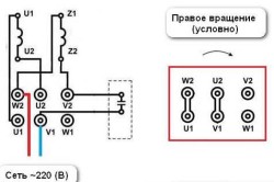
Such motors, which are rare nowadays, can however be used to drive stuffing box compressors. To change the direction of rotation of the motor, it is enough to crosswise change the connection point of the starting and main windings.
As an example in Fig. shows how the end of the starting winding became the beginning, and the beginning became the end.
Note that in this case the direction of current flow through the starting winding has changed to the opposite, which makes it possible to give an impulse at the moment of starting magnetic field in the opposite direction.
Finally, we also note two-wire motors with a “Fraget coil” or a “phase-shifting ring”, widely used to drive small fans with low resistance torque (usually blades). These motors are very reliable, although low torque, and there are no particular problems when plugging them into the mains since they only have two wires (plus ground, of course).
B) Start relays
Regardless of the design, the job of the starting relay is to turn off the starting winding as soon as the engine reaches approximately 80% of the rated speed. After this, the engine is considered running and continues to rotate only with the help of the working winding.
There are two main types of starting relays: current relays and voltage relays. We will also mention triggering using the CTP thermistor.
First, let's study the current starting relay
This type of relay is typically used in small single-phase motors used to drive compressors whose power does not exceed 600 W (home refrigerators, small freezers...).
Sometimes the question arises of how a single-phase motor is connected to power supplies and networks. Single-phase asynchronous electric motors are the most common, since they are installed on the vast majority of various household appliances and equipment (computers, etc.). Sometimes such engines are purchased and installed in workshops, garages, etc. to ensure that some work is carried out (for example, lifting a load).
Single-phase asynchronous electric motors are installed on the vast majority of various household appliances and equipment.
The work requires connecting a single-phase electric motor, and this is quite difficult for a person who does not understand electrical engineering and electric drives. The difficulty stems from the fact that the motor has many terminals, and the amateur experiences difficulties due to the fact that he does not know which terminal should be connected to the power source. Therefore, this material examines connection issues specifically for the average citizen who has no idea about the electric drive and does not understand electrical engineering.
Description of the machine
Single-phase electric motors are usually called asynchronous single-phase electrical machines with low power. The magnetic core of such machines has a two-phase winding, which is divided into a starting (starting) and a main winding. The need for 2 windings is as follows: they must cause the rotor of the electric propulsion (single-phase) to rotate. At the moment, such devices are conventionally divided into 2 categories:

- Presence of starting windings. In this embodiment, the starting winding is connected through a starting capacitor. When the launch is complete and the machine has developed rated speed rotation, the starting winding is disconnected from the power supply. After which the engine continues to rotate on the working winding connected to the network (the capacitor charges during startup and turns off the starting winding). The required capacitor volume is usually indicated by the machine manufacturer on a plate with all the parameters (as a standard it should be on all engines).
- Machines with working capacitors. In such electrical machines, the auxiliary windings are always connected through capacitors. In this case, the volume of capacitors is determined by the design of the engine. In this case, the capacitor remains switched on even when the machine reaches the nominal operating mode.
To correctly connect an electrical machine, you must be able to determine (or know) how the starting and operating windings are wired, as well as their characteristics.
It is worth noting: these windings differ in the conductors used (their cross-section), as well as in the turns. So, for the working windings, conductors of a larger cross-section are used, and they have a larger number of turns. It is important to know that the resistance of the working windings of different machines is always less than the resistance of the starting/auxiliary windings. In this case, measuring the resistance of the motor winding is not difficult, especially if special multimeters are used.
Based on what has been described, it is worth giving some examples.
Connection examples
Here we will consider 3 options for propulsion that differ from each other.
Option #1. The mover has 4 outputs. First, the ends of the windings are found (usually they are arranged in pairs, so seeing them is not difficult).
There can be 2 options for the location of the pins: either all 4 in one row, or 2 in one row and 2 in the second. In the first case, it is easier to determine the windings: the first pair is one winding, the second is another.
In the second case, you can get confused between the windings. The most common option is when one vertical row is one winding, the other is the second. But it is worth knowing that the multimeter will give a value of infinite resistance if the terminals of different windings are selected. And then everything is simple.
The resistance of the windings is determined: where there is less resistance, it is the working one, and where the greater resistance is the starting one.
The connection is made as follows: 220 V is supplied to the thick wires, and one starting terminal is connected to the working terminal. In this case, there is no need to worry about the correct connection of the terminals - the operation of the machine and the direction in which the rotation occurs will not change depending on which end was connected to which. The direction of rotation changes due to the change in the connection ends of the starting winding.
The second option is when the machine has 3 outputs. In this case, when measuring the resistance between the windings, the multimeter will show different values - minimum, maximum, average (if measured in pairs). Here the common end, which will be at the minimum and average value, is one of the ends of the connection, the other terminal for connecting the network is the one that has the minimum value. The output that remains - the output of the starting winding - must be connected to the capacitor and to one of the ends of the network power supply. In this case, it is impossible to independently change the direction of rotation.
The last example. There are 3 pins, and measurements of the resistance between the pins in pairs showed that there are 2 absolutely identical values and one greater (about 2 times). Such movers were often installed on old ones and are installed on modern washing machines. This is exactly the case when the windings of the machine are identical, so it makes absolutely no difference how the windings are connected.
How to apply this in practice? This is the most frequently asked question, because connecting tools (grinders, hammer drills, screwdrivers, etc.) can be difficult. This is sometimes due to the fact that the tool uses a commutator motor, which often works without starting devices. Let's consider this option in more detail.
Starting an electric motor with a commutator

This case is the most common. In the chapter above it is designated as example No. 3. Such motors are often used for household devices, because they are simple and cheap.
Usually the ends of such engines are numbered. Therefore, to connect, you should connect pins 2 and 3 to each other (one comes from the armature and the other from the stator), and connect numbers 1 and 2 to the power source.
You should know that if you connect such a machine without special electronic devices, then it will only produce the maximum number of revolutions and speed adjustment will be impossible. In this case, there will be a large starting current and jerking force at start-up.
If a change in the direction of rotation of the propulsion is required, then the connection of the stator or armature leads should be reversed.
Practical connection
If there is a motor that should be connected to the network, then you need to carefully study its plate, which shows the nominal values of the machine and the capacitor (or several capacitors). Next, using the name of the electric machine model, it is recommended to find a diagram.
The connection diagram for a single-phase electric motor may be different for different devices, so it is recommended to select a diagram for a specific option. Otherwise, problems may arise, including complete failure of the propulsion unit (when it burns out). Next, you should select a capacitor (if it has failed or is missing). The selection is carried out according to special tables that are in the reference literature.
Let's take a washing machine as an example. recent years release. A commutator or three-phase motor is usually used there. If there is a three-phase motor, it can only be started by connecting a special starting unit, which must be selected for the specific model of the washing machine.
If there is a collector machine, about 7 wires (±1) will be brought out to the terminal block, excluding the grounding terminal (it is marked with the appropriate sign, and a yellow-green wire goes to it). A pair of pins usually has a tachometer; they are not connected to the network. And 2 outputs each have the stator and rotor of the electric machine and are marked alphanumerically (for example, A1-a1, or A-a). The first letter (capital) indicates the beginning of the winding, the second the end. The other winding is designated by the next letter of the Latin alphabet. Power is supplied to the beginning of the rotor and the end of the stator winding. To do this, you need to decide in advance on the winding (which one comes from where). After which the free terminals of the windings are connected using a jumper.
After this, you should carry out a test run of the device, observing safety regulations.
Single-phase asynchronous electric motors with a power of up to 1 kW, rarely up to 2 kW, are widely used in conditions where there is only a single-phase network, for example, to drive mechanisms of various devices, electrified tools, in household mechanisms, etc. If the motor winding is powered single-phase current, then the electromagnetic field in it will not be rotating, as in three-phase machines, but pulsating, the energy performance will be worse than that of three-phase machines, but. the starting torque will be zero, i.e. the engine will not start without special devices. Therefore, in the stators of single-phase motors, two windings are installed, which are often also called winding phases. One of them is main, or working, the other is auxiliary. The windings are located along the stator slots so that their axes are shifted relative to each other in space by an electrical angle of 90° (Fig. 1).
Fig.1. Winding axes of two- and single-phase motors: a - location of coils of different phases in the stator slots; b - conventional image of the winding phases.
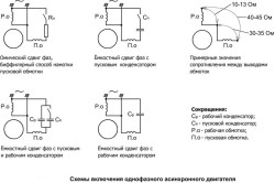
If the phases of the winding currents are not the same, i.e., shifted in time, then the electromagnetic field in the motor stator becomes rotating. The energy performance of the engine improves and starting torque appears. When the phases of the currents are shifted by an electrical angle of 90° and the MMF windings are identical, the field becomes circular and the efficiency of a single-phase motor will be greatest. This can be achieved by making both motor windings identical and connecting a capacitor in series to one of them (Fig. 2.a). Such motors are called single-phase capacitor motors.

Rice. 2.. Connection diagrams for single-phase motors: a - with a permanently switched on capacitor (capacitor motors); b - with working and starting capacitors; c - with a starting element; Ср - working capacitor; Sp - starting capacitor; PE - starting element.
The capacitance of the capacitor required to obtain a circular field depends on the active and inductive resistance of the motor windings and on its load. For single-phase capacitor motors, the capacitor is designed so that the field is circular at rated load. It is connected in series with one of the phases of the windings for the entire operating time. This capacitor is called the working capacitor and is designated Wed. When starting the engine, the capacitance of the working capacitor is insufficient to form a circular field and the starting torque of the engine is small. To increase the starting torque, a second starting capacitor (Sp) is connected in parallel with the working capacitor. The total capacitance of the starting and operating capacitors ensures that a circular rotating field is obtained during engine starting and its starting torque increases. After the engine accelerates, the starting capacitor is turned off, and the working capacitor remains turned on (Fig. 2.b). Thus, the engine starts and runs at rated load with a rotating circular field.
Rice. 3. Scheme of a single-layer concentric winding with m = 2, z = 16, 2р = 2,
performed in a waddling manner.
The stators of most single- and two-phase motors use random single-layer windings with concentric coils (Fig. 3). They have either four terminals - the beginnings and ends of the main and auxiliary phases, or only three. With three outputs, the ends of the main and auxiliary phases are connected to each other inside the housing and a wire is led out from the place where they connect to the common point of the winding.

Rice. 4. Scheme of a single-layer concentric winding with m = 2, z = 24, 2р = 4, q = 3, made with “combed” coils.
To reduce the overhang of the frontal parts of the coils, single-layer windings are often waddled. If the number of slots per pole and phase is even, then the waddling windings are essentially no different from the same windings of three-phase machines. If the number q is odd, then the large coils in groups are made “combed”, that is, the frontal parts of half of their turns are bent in one direction, and the other half in the other direction (Fig. 4).
The need to install capacitors increases the cost of single-phase motors, increases their size and reduces reliability, since capacitors fail more often than motors. Therefore, most single-phase asynchronous motors are designed to operate with only one - the main winding. However, in order for them to be started, a second winding is installed - an auxiliary winding, which is often called a starting winding. It is intended only to create a rotating field when starting the engine. Such single-phase motors are called motors with a starting phase (or with a starting winding).
The phase shift of the currents of the main (working) and starting windings is achieved by changing the resistance of the starting winding by connecting in series with it the so-called starting element (Fig. 2.c) - a capacitor or resistor (most often a cheaper one is used - a resistor).
Starting windings, as a rule, differ from working windings in the number of turns, the number of coils, and the cross-section of the wire. They usually occupy 1/3 of all stator slots. The remaining 2/3 of the slots contain the working winding. The connection diagrams and number of poles of the working and starting windings are the same (Fig. 5).

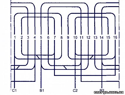
Rice. 5. Scheme of a single-layer concentric winding of a single-phase motor with a starting phase with z = 24, 2р = 4; C1-C2 is the main phase, B1-B2 is the starting phase.
To avoid installing resistors that must be designed for the full starting current, in many single-phase motors the starting winding is made with an increased starting phase resistance. For this purpose, the starting winding is wound from a wire of a smaller cross-section than the working one, or it is made with partially bifilar winding.
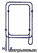
Rice. 6. Formation of bifilar turns.
In this case, the length of the wire increases, its active resistance increases, and the inductive resistance and MMF remain the same as without bifilar turns. To form bifilar turns, the starting winding coil is made of two sections with opposite winding directions (Fig. 6). One section, the winding direction of which coincides with the polarity required to start the machine, is called the main one, and the section with counter winding is called bifilar. The latter always has fewer turns than the main one. In winding diagrams, coils that are partially bifilar wound are designated as a loop (Fig. 7a). In Fig. Figure 7b shows a winding diagram with a starting phase having a partially bifilar winding. The main winding is made of concentric waddling coils. The loops on the starting phase coils indicate that the coils are made with partially bifilar winding.

Rice. 7. Diagram of a winding with coils having bifilar turns: a - image of coils with bifilar turns on a winding diagram, b - diagram of a winding with z = 24, 2р = 4.
In a winding with bifilar coils, it must be taken into account that in each auxiliary phase coil some of the turns are wound counter-winding. This reduces the number of effective conductors in the groove, neutralizing the effect of the same number of turns wound in the main direction, therefore, to find the number of effective turns in the coil (effective conductors in the groove), it is necessary to subtract twice the number of counter-wound turns from the total number. If, for example, there is a coil in the groove, in which there are only 81 turns, of which 22 are wound counter-winding, then the number of effective conductors in the groove will be: 81-2-22 = 37.
To determine the number of counter-wound turns with a known total number of conductors in the slot and the number of effective conductors in the slot, it is necessary to perform the reverse action, i.e., subtract the number of effective conductors from the total number and divide the resulting result by two. With a total number of conductors of 81 and an effective number of 37, the number of counter-wound turns should be: (81-37)/2 = 22.
A bifilar coil can be obtained by placing two coil sections in the same slots, one of which rotates 180° around an axis parallel to the slots. The right and left sides of the rotated section are swapped.
The starting winding of single-phase motors is designed only for short-term operation - while the motor is starting. It must be disconnected from the network as soon as the engine accelerates, otherwise it will overheat and the engine will fail. Such motors are used, for example, to drive compressors in all household refrigerators, drive washing machines etc. The starting protection relay installed on refrigerators and washing machines turns on both motor windings, and after it accelerates, turns off the starting winding. The engine operates with one working winding turned on.
Home » Electrical equipment » Electric motors » Single-phase » How to connect a single-phase electric motor through a capacitor: starting, operating and mixed connection options
How to connect a single-phase electric motor through a capacitor: starting, operating and mixed connection options
Asynchronous motors are often used in technology. Such units are distinguished by their simplicity, good performance, low noise level, and ease of operation. In order to asynchronous motor rotated, a rotating magnetic field is required.
Such a field is easily created in the presence of a three-phase network. In this case, it is enough to place three windings in the motor stator, placed at an angle of 120 degrees from each other, and connect the appropriate voltage to them. And the circular rotating field will begin to rotate the stator.
However household appliances usually used in homes that most often only have a single-phase electrical network. In this case, single-phase asynchronous motors are usually used.
Why is it used to start a single-phase motor through a capacitor?
If one winding is placed on the motor stator, then when an alternating sinusoidal current flows, a pulsating magnetic field is formed in it. But this field will not be able to make the rotor rotate. To start the engine you need to:
- place an additional winding on the stator at an angle of about 90° relative to the working winding;
- connect a phase-shifting element, for example, a capacitor, in series with the additional winding.
In this case, a circular magnetic field will arise in the motor, and currents will arise in the squirrel-cage rotor.
The interaction of currents and the stator field will cause the rotor to rotate. It is worth recalling that to regulate starting currents - control and limit their magnitude - they use a frequency converter for asynchronous motors.
Options for switching circuits - which method to choose?
- launcher,
- workers,
- starting and running capacitors.
The most common method is the scheme with starting capacitor .
In this case, the capacitor and starting winding are turned on only when the engine starts. This is due to the property of the unit continuing its rotation even after the additional winding is turned off. For such activation, a button or relay is most often used.
Since the start-up of a single-phase motor with a capacitor occurs quite quickly, the additional winding operates for a short time. This makes it possible to save money by making it from wire with a smaller cross-section than the main winding. To prevent overheating of the additional winding, a centrifugal switch or thermal relay is often added to the circuit. These devices turn it off when the engine reaches a certain speed or when it gets very hot.
The circuit with a starting capacitor has good engine starting characteristics. But the performance characteristics with this inclusion deteriorate.
This is due to the operating principle of an asynchronous motor. when the rotating field is not circular, but elliptical. As a result of this field distortion, losses increase and efficiency decreases.
There are several options for connecting asynchronous motors to operating voltage. The star and delta connection (as well as the combined method) have their advantages and disadvantages. The selected switching method affects the starting characteristics of the unit and its operating power.
Operating principle magnetic starter is based on the appearance of a magnetic field when electricity passes through a retractor coil. Read more about engine control with and without reversing in a separate article.
Better performance can be obtained by using a circuit with working capacitor .
In this circuit, the capacitor is not turned off after starting the engine. By correctly selecting a capacitor for a single-phase motor, you can compensate for field distortion and increase the efficiency of the unit. But for such a circuit the starting characteristics deteriorate.
It is also necessary to take into account that the choice of capacitor capacitance for a single-phase motor is made for a certain load current.
When the current changes relative to the calculated value, the field will move from a circular to an elliptical shape and the characteristics of the unit will deteriorate. Basically, to ensure good characteristics When the engine load changes, it is necessary to change the capacitance value of the capacitor. But this may complicate the switching circuit too much. 
A compromise solution is to choose a scheme with starting and running capacitors. For such a circuit, the operating and starting characteristics will be average compared to the previously discussed circuits.
In general, if a large starting torque is required when connecting a single-phase motor through a capacitor, then a circuit with a starting element is selected, and if there is no such need, with a working element.
Connecting capacitors to start single-phase electric motors
Before connecting to the motor, you can check the capacitor with a multimeter for functionality.
When choosing a scheme, the user always has the opportunity to choose exactly the scheme that suits him. Typically, all winding terminals and capacitor terminals are led out into the motor terminal box.
The presence of three-wire wiring in a private house requires the use of a grounding system. which you can do yourself. You can find out how to replace electrical wiring in an apartment using standard diagrams here.
If necessary, you can upgrade the circuit or independently calculate a capacitor for a single-phase motor, based on the fact that for each kilowatt of unit power, a capacitance of 0.7 - 0.8 μF is required for the operating type and two and a half times larger capacity for the starting type.
When choosing a capacitor, it is necessary to take into account that the starting one must have an operating voltage of at least 400 V.
This is due to the fact that when starting and stopping the engine in electrical circuit due to the presence of self-induction EMF, a voltage surge occurs, reaching 300-600 V.
- Single-phase asynchronous motor is widely used in household appliances.
- To start such a unit, an additional (starting) winding and a phase-shifting element - a capacitor - are required.
- There are various schemes for connecting a single-phase electric motor through a capacitor.
- If it is necessary to have a larger starting torque, then a circuit with a starting capacitor is used; if it is necessary to obtain good engine performance, a circuit with a running capacitor is used.
Instructions
Examine the engine carefully. If it has six jumper pins, check the order in which they are installed. If the motor has six terminals and no block, the terminals must be collected in two bundles, and the beginnings of the windings must be collected in one bundle, and the ends in the second.
If the motor has only three terminals, disassemble the motor: remove the cover from the side of the block and look for the connection of three wires in the windings. Then disconnect these three wires from each other, solder the lead wires to them and combine them into a bundle. Subsequently, these six wires will be connected in a triangle pattern.
Calculate the approximate capacitance of the capacitor. To do this, substitute the values into the formula: Cmf = P/10, in which Cmf is the capacitance of one capacitor in microfarads, P is the rated power (in watts). And here's what else is important: the operating voltage of the capacitor must be high.
Please note: if you turn on the volt capacitors serial connection method, then half the capacity will be “lost”, but the voltage will double. From a pair of such capacitors a battery of the required capacity can be assembled.
When connecting capacitors, take into account their peculiarity: the fact is that after disconnecting the capacitors, they retain voltage at the terminals for a long time. In view of this, such capacitors pose a danger to life, because the risk of electric shock is too high.
The starting resistance Rn is determined experimentally. To increase the torque when starting the engine, connect the starting capacitor simultaneously with the working capacitor (it is connected in parallel with the working capacitor). Calculate the capacity of the starting capacitor using the formula: Cp = (2.5 to 3)Cp, in which Cp is the capacitance of the working capacitor.
Capacitors are actively used in the automotive industry in high-tech electrical equipment. They are included in many components and mechanisms of the car, from the power plant control unit to the power supply circuits of the audio system.
Instructions
Without a capacitor, stable operation of the power supply is impossible. It must be included in electrical diagram, in addition, have a certain capacity. This part, in fact, dampens voltage surges in electrical network like a shock absorber does, smoothing out road irregularities. At the same time, it accumulates excess electricity and releases it as needed. This protects the elements from burnout and wear. Which capacitor is recommended for your car is usually indicated in the documentation for it. If the documents are lost, contact a specialized car service center.
Choosing the right capacitor that is right for you is an important task. After all, this market is developing dynamically, provoking developers and manufacturers to release new models. And the number of manufacturers is constantly growing. However, everything