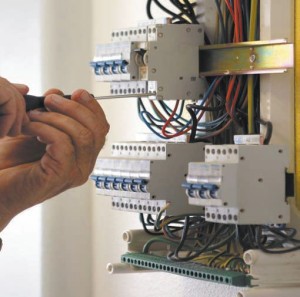
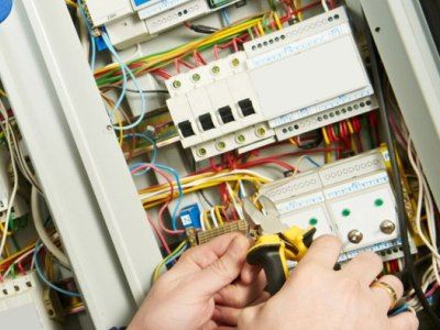
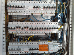
Assembling a distribution board is a rather complex process, which is not recommended without some experience in the energy supply sector. After all, the supply of electricity to the house depends on the correct assembly and installation of the distribution board. We’ll learn more about how to do the electrical installation yourself with your own hands.
Do-it-yourself electrical installation of a private house: technology and work procedure
Assembling and installing a distribution panel is a rather complex process, for which you must have some experience in carrying out this type of work. There are several stages in assembling the distribution panel. As a result, the resulting shield should be safe to use, convenient, and each of its elements should become part of one large system. The main functions of the distribution board in the house are:
- monitoring energy consumption;
- control of consumption and various types of circuits;
- selective protection.
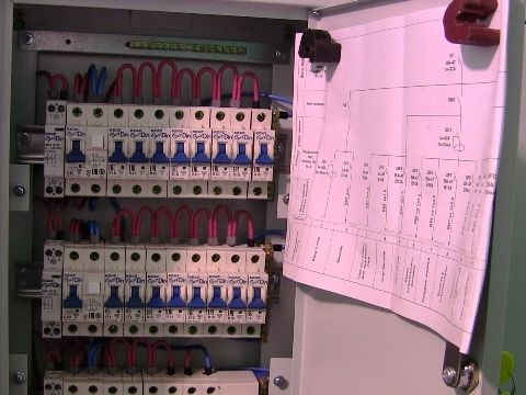
To organize a shield, you must have minimal skills in performing electrical installation work. At the initial stage of work, the electrical panel is designed. This work is performed after installing all circuits and laying wires. At the initial stage of work, working drawings are developed and a scheme for performing installation work is determined.
Start by organizing lists of all electrical consumers in the house, that is, you need to identify each wire that goes to the panel. To designate it, use special numbering.
The organization of the power supply system is carried out in the same way, so once you understand the principle of operation, drawing up a diagram will not be difficult. Separately mark the sockets located in each room, separately the lighting devices. If there are devices in the house that are not connected to the outlet, but are directed directly to work from the switchboard, they are also indicated in the design documentation.
That is, when drawing up a project for installing an electrical panel, it is necessary to indicate sockets separately for each room, as well as lighting devices and equipment that connects directly to the panel. The connection of each device through an individual RCD is highly compact and easy to use, however, such a circuit requires a large number of wires for its organization and it is impressive in size.
Please note that a special box is used to connect a telephone and other devices that consume little electricity. After creating the lists, all data is entered into the table.
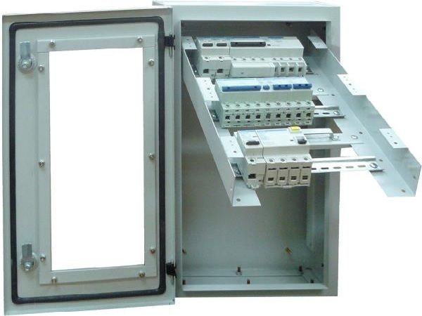
At the next stage, a diagram for performing electrical installation work is created. Each modern switchboard is distinguished by the presence of modules on which standardized devices are fixed. The diagram must indicate the number of modules and their type - single, double or triple. Please note that the order in which the rows are formed depends on the number of modules.
Next, a selection of devices is made with the help of which the electrical installation will be organized. First of all, you need to decide on the body part. For these purposes, you will need to have the right box. If the work is carried out in an apartment, then using the built-in option is sufficient. For a private home, a device made of plastic or metal would be optimal. Pay attention to the quality of the material from which the switchboard body is made. Leading European manufacturers produce some of the most best models scutes. If there are a large number of wires in the apartment, we recommend purchasing a panel with removable walls. Some models offer the possibility of moving special slats.
Please note that when choosing a box or body part of a panel, you should always leave a reserve for several modular wires.
At the next stage of electrical installation at home, you select modular devices for organizing the panel yourself. To do this, it is necessary to purchase devices in the form of circuit breakers, differential devices, contactors, relays; modular sockets, buses, transformers, power elements, and devices providing monitoring and control are installed on rails.
When choosing these devices, pay attention to the following characteristics:
- optimal value of labor force;
- the speed at which the machines begin to operate;
- type of device shutdown;
- optimal contactor response value.
These parameters are determined individually for each circuit. Please note that the system must be balanced. If there is low power consumption, installing an overly powerful machine will be inappropriate, since the system will not be reliably protected from overvoltage.
Switching off the circuits must be individual and independent, thus achieving the necessary selectivity. If problems arise, the circuit on which there is a problem will be turned off, and all others will work.
The machines must be equipped with a special setting that determines their operation time. For example, if there are several circuit breakers with a capacity of twenty-five amperes, the consumer must install a device that ensures they turn off within 0.2 seconds, and the next machine turns off after 0.5 seconds.
The value of the rated current of the protection device is determined comprehensively in combination with subordinate circuit breakers. This value must exceed the rated current so that the machine is initially turned off, and then the devices. Otherwise, there is a risk of damage to the protection device, which is more expensive than a conventional machine.
The tripping current value of the protection device characterizes its sensitivity. Devices that provide quick protection are installed in bathrooms, near washing machines, boilers and other expensive equipment. In order to ensure fire safety devices, it is necessary to install a model that has an operating current of 150-300 milliamps.
DIY electrical installation video:
Next, you should purchase additional materials in the form of slats and good tires. The rail has the shape of a bar on which holes are located. Current-carrying sections of busbars must be closed using covers. In addition, you should purchase a bus that will provide zero connection and grounding.
If you need to connect more than one conductor to the bus, you must additionally stock up on terminal blocks, with the help of which you can branch the wire neatly and reliably. Their design is also carried out on a special rail.

To ensure current transfer between devices modular type in the form of machines and devices protective shutdown, it is necessary to additionally use insulated combs. With their help, it is possible to achieve good contact between devices, as well as the ability to withstand high voltages, save time and improve energy-economic indicators.
It is possible to purchase devices of different lengths; for additional insulation, they are equipped with plugs in order to connect two or three rows at once.
To distribute the phase between the rows, use one piece of wire, which is crimped with a special tip. The length of such a wire must exceed one centimeter. To clamp two conductors inside the machine at once, use a double-type tip. Highlight large number lugs designed for different sized cores and different numbers of wires.
Do-it-yourself electrical installation diagram and panel assembly
Before starting work, arrange additional lighting above the work area. On a separate table, install all the tools that will be needed during the work process. Install brackets on the wall that allow you to temporarily attach the wire. Install the previously created shield mounting diagram in a visible place so that it is always in front of your eyes. Check availability necessary equipment. Take care to de-energize the input wire.
Features of do-it-yourself electrical installation in a private house:
- Initially, you should start by assembling the distribution box;
- remove all plugs, make holes for all wires;
- install special slats, as well as tires and neutrals;
- dismantle the door, if necessary;
- install mounting brackets.
Initially, all wires are adjusted in length, but keep in mind that a small margin should still be present. If there are a large number of wires on the wall, one of them is supplied from the top, and the second from the bottom. Therefore, you need to group and distribute the wires in advance. Next, the outer insulation on the cable is removed. For these purposes, use a special tool that will prevent damage to the primary insulation.
Please note: when removing the outer insulation, it is possible to accidentally touch the wire markings; in this case, the wire must be labeled with a marker. Therefore, when cleaning, also mark the wires. For these purposes, use masking tape, which already has a mark indicating the purpose of the cable.
A conductor and an input-type cable are installed in the inside of the shield. At the same time, the wires are leveled in one layer. Next, the types of machines on which the wires are connected are determined.

The next stage is the installation of modular devices on rails. In relation to the circuit, observe the nominal values between devices. Initially, the residual current device is fixed, then the circuit breakers are installed. At the final stage, the installation of independent circuit breakers and additional modular devices is carried out.
Please note that the installation of all automation is carried out gradually. It is possible to install one rail and automation on it, and then the next rails. Next, the meter is installed and its location on the surface of the shield is determined.
One of the main processes of do-it-yourself electrical installation in a country house is switching. To do this, the core of each wire is connected to a specific circuit on the machine or bus. During the switching process, you should pay attention to the following recommendations:
- work is carried out in a certain order - for example, from left to right or vice versa;
- connecting the cores at the fixing points, with the excess being cut off with a knife;
- The installation of cables inside the switchboard is also carried out in compliance with a certain order, for example, in a vertical or horizontal direction, while the wires only need to be turned at an angle of 90 degrees;
- stripping of wires is carried out approximately 10 mm; a special tool is used for this purpose;
- it is necessary to install special plugs in the form of tips on the surface of the soft cores;
- the ends of the wire are mounted under the end parts of the machine;
- voltage is supplied to the machine box from the top, and the conductor is supplied from the bottom, this standard is generally accepted;
- check the reliability of the wire connections, make sure that the copper wires do not protrude from under the machine;
- To assemble several wires together, use plastic ties and install them behind the surface of the rails.
Next, the input cable is connected. To do this, the wire must be clamped in front of the main circuit breaker in the form of phase and zero; one of the cores, which is responsible for grounding, is installed on the bus. The phase and neutral wires are connected to the meter or their further wiring is carried out in relation to the circuit.
At the final stage of ceiling electrical installation, you connect the products yourself and alternately supply the load to each line. If the system is working properly, apply voltage to all lines. To test each protection device, press a specific button. Turning off the voltage on the circuit is evidence of the correct operation of the device. Label the automatic devices, install the diagram on the door, and install the cover on the body part.
The duration of operation of the shield determines the quality of electrical installation work. wooden house hands. Using high-quality materials from trusted suppliers allows you to end up with a good electrical panel, which is characterized by uninterrupted operation and good power supply to the house.
DIY electrical installation in a wooden house video:
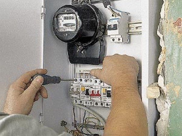
Many novice craftsmen, without proper experience in electrical engineering, do not risk assembling an electrical distribution panel in the house with their own hands, preferring to delegate this work to more experienced specialists. In many cases, such indecisiveness is caused by insufficient experience working with modular machines that are installed in a protective box (box).
In addition, companies and services involved in energy supply are very critical of the possibility of self-installation by users of a meter installed on the incoming distribution panel of the house.
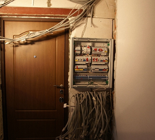
Input of electricity into the distribution panel
These reasons force apartment and house owners to order expensive installation services from licensed specialists and wait a long time for them, even if they have the opportunity, tools, desire and skills to assemble it with their own hands. home switchboard.
Home electrical panel
Preface to the step-by-step instructions
If it is possible to agree with official services about self-installation meter, with subsequent installation of seals by authorized officials, then it will be much more profitable to assemble the panel yourself, installing and connecting the modules in order to save your home budget.
This article will discuss specialized technical nuances for installing the panel and connecting modular elements inside the box - many users imagine the diagram and principle of electrical energy distribution inside the electrical panel, but do not have practical installation skills.
Assembly electrical panel
Since the selection of wires, calculation of their cross-section and selection of protective circuit breakers, as well as the principles of dividing electrical wiring in a house into groups of consumers have already been discussed in other topics of this resource, the main emphasis will be placed on working with the element base - the panel, modular circuit breakers, their terminals and wires .
Electrical installation work
But before you start work and try to assemble the switchboard yourself, you must obtain permission to carry out the installation yourself.
Separation of powers for electrical installation work
Having firmly decided to install a distribution panel in the house with your own hands, you need to negotiate with the official energy supply services how electricity will be supplied to the house - directly into the meter with an unbroken cable from the power line, or through a circuit breaker. According to the PUE standards, in front of the meter in mandatory must stand circuit breaker.

Quote from PUE
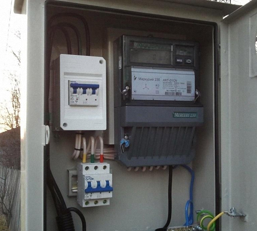
But often, official services ignore this rule, fearing the possibility of the user illegally connecting to the terminals of the machine, bypassing the meter in order to steal electricity. The best option would be to install an incoming circuit breaker installed in a sealable box inside the panel.
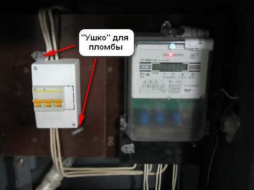
The input machine is sealed
It is also possible to install a sealable box for the introductory machine on external wall Houses. This precaution is especially necessary if air flow is carried out into a wooden house.

Introductory machine on a wooden facade
Also, very often in such cases, a meter is installed and sealed in the outer box, with machines before and after it, and the output goes inside the house into a distribution panel, which the user has the right to assemble himself, with his own hands, without obtaining additional permits.
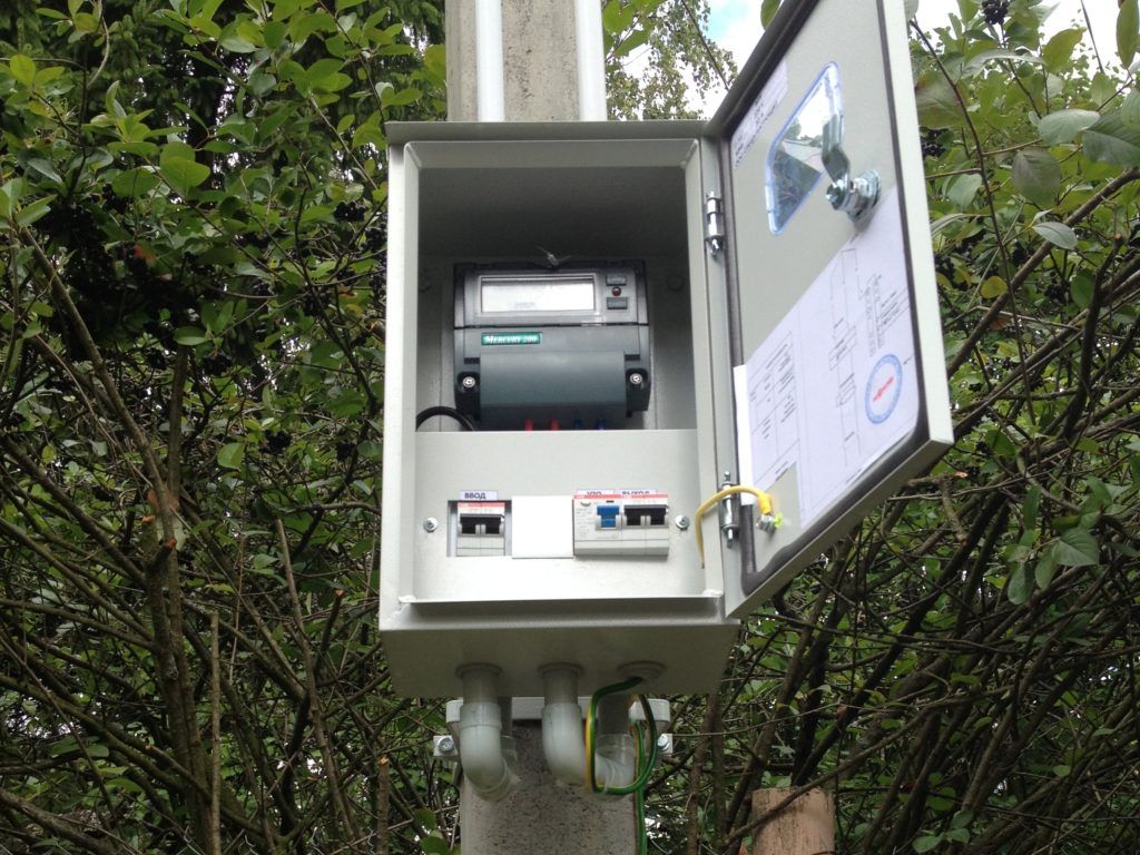
An outdoor box with machines and a counter is installed on a pole near the house
Thus, there is a division of responsibility and there is no violation of the rules and legality of electrical installation work.
Box selection criteria
The selection of a shield for a home is made according to the following criteria:

Appearance and functionality of boxes
Conventionally, distribution boards can be divided into two types. The first type resembles bulky apartment buildings and enterprises - a cabinet with a closed door and a switch protruding outwards.
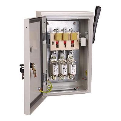
Electrical cabinet with switch and fuses
A home panel of this type may have a lid that tightly covers all internal elements, or there may be only one central circuit breaker for quick shutdown. There may also be a window for checking meter readings. In such boxes the lid is locked with a key.

Box cover with a slot for taking meter readings
If the shield is installed in a place inaccessible to unauthorized persons, then access to the control of the machines is not limited, but all their connections are hidden behind a removable protective panel that has a transparent decorative cover to prevent the entry of dust and dirt.
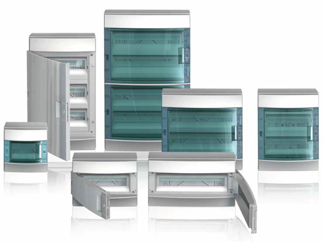
Apartment shields with transparent protective covers
To ensure that there is no empty space in the protective panel if the number of machines is less than the calculated one, the manufacturer provides break-away partitions that are removed during the installation process, freeing up a niche for the module.

Removing partitions in panels for modules using the breaking method
You can remove this partition with your own hands by pressing with your fingers (there are special cuts along which the break occurs), or cut it off with a knife.
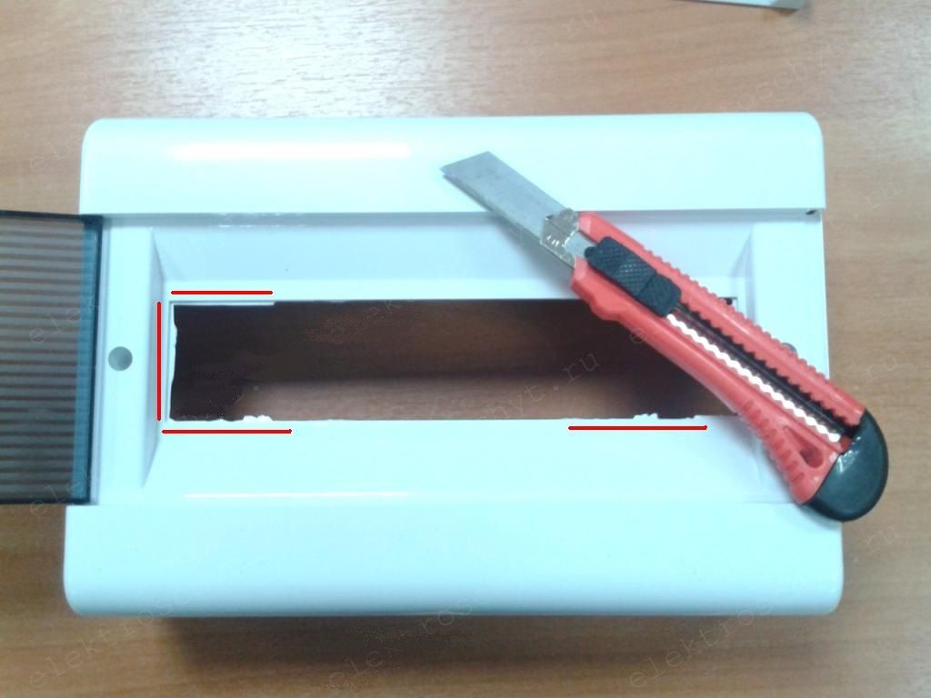
Removing partitions with a knife
Fixing modules
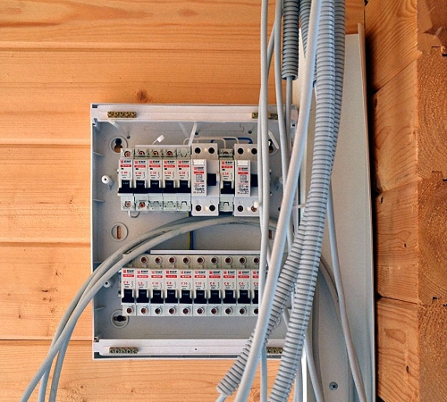
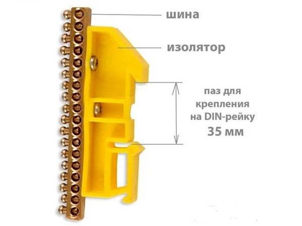
Modern protective devices and the machines have a unified mounting system on a so-called DIN rail, 35mm wide, which allows you to assemble the panel quickly and efficiently, without spending a lot of time on installing each module. Therefore, as a rule, electrical distribution boxes for houses and apartments are produced with a DIN rail already attached inside.
DIN rails on removable bracket
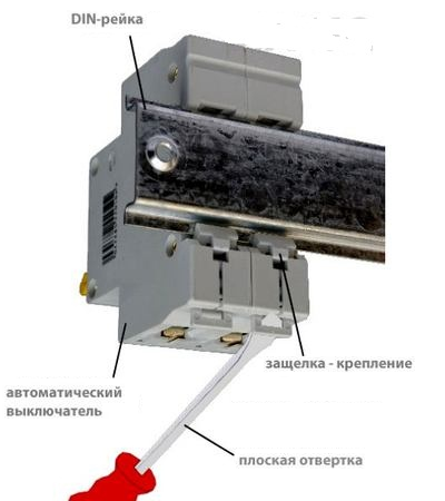
When choosing a shield, you need to make sure that this fastening device is available, so as not to waste time and effort on attaching the DIN rail with your own hands, having first cut off the required length. The special design of meters and modular machines allows them to be mounted on a DIN rail by snapping them into place. To do this, you need to put the module on the upper edge of the rail, and then press on its lower part so that the latch snaps into place.
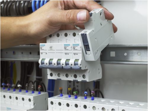
Installing the module on a DIN rail
Installation of high-quality machines does not require much effort and does not cause any problems. If for some reason the latch does not snap into place, then it is necessary to use a screwdriver pry the latch- then the machine will fall into place.
Installing and dismantling the module on a DIN rail
To dismantle the module, it is necessary to pull back the locking latch.
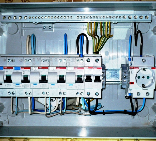
Zero and ground buses
Another important component of modern distribution boxes is the zero (N) and ground (PE) bus. Since, according to existing PUE standards, each apartment or house must have grounding in the form of an additional protective conductor PE, the panels, as a rule, are produced with an installed insulated zero bus, to which lines converge, each protected by its own circuit breaker, and a bus attached to the housing grounding, from which grounding conductors diverge to each outlet.
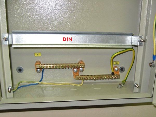
Zero bus N and ground bus PE, initially installed in the panel
These buses have holes for inserting wires of various diameters. The conductors are fixed by tightening the fixing bolt perpendicular to the axis of the wire.
It must be remembered that in the event of a branching line coming after the RCD, the neutral conductors in the panel must be connected to an isolated bus not connected to the common zero. If several RCDs are used, then each must have its own insulated zero bus mounted on a DIN rail in the panel.
Insulated busbar for neutral conductor
Therefore, when choosing a panel for connecting and distributing lines protected by an RCD, it is necessary to provide space for the appropriate number of insulated zero busbars.
Electrical connections in the box
The order of installation of modules in the panel, as a rule, is not regulated, but it would be more appropriate to place the machines from left to right as the rated current of the devices decreases.
This principle is also determined by the fact that very often jumpers are used to branch a phase wire into several modules - in this case, the first of them must withstand the total current of all machines, and subsequent ones can be made with a wire of a smaller cross-section.
Jumpers must be made from insulated single-core wire with a pre-calculated cross-section, but not less than 2.5 mm².
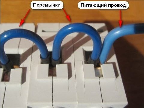
Connecting modular machines using jumpers
To branch the phase conductor, in order not to use unreliable jumpers, professional electricians, when assembling panels, use special buses called ““, which are inserted into the terminal socket of modules installed next to each other.

Connecting modules using a comb
If a comb is used, installation and assembly of the shield is greatly simplified, but the machines used must have the same height and thickness, otherwise the conductive protrusions of the busbar will not coincide with the terminals. But, if you cannot do without jumpers, then to make them it is necessary to strip the wire of insulation from one end to a distance no greater than the depth of immersion of the bare conductor into the terminal socket. Having placed the wire, you need to bend it towards the desired connection terminal, then bite it off with wire cutters and strip it of insulation.
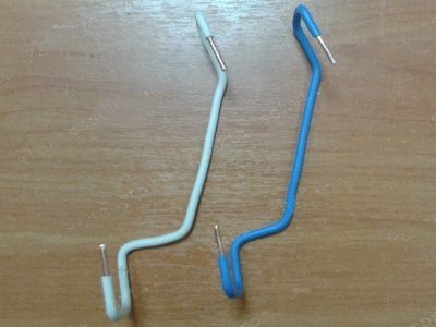
Jumpers, curved for connecting modules
You can give the jumper the desired shape directly with your own hands or using pliers. Having a similar template, you can do required quantity jumpers for making all connections in the panel.
Wiring of jumpers and modules
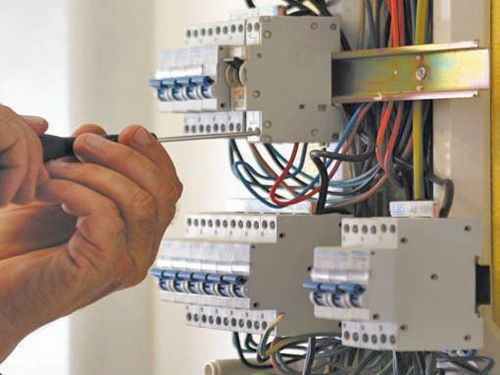
The process of assembling the panel must begin from the input machine, connecting each module, checking the connection according to the diagram.
Approximate electrical panel diagram
About drawing up electrical wiring diagrams for different apartments and houses can be read at. Having chosen the appropriate scheme and made the necessary additions, you must strictly adhere to it.
It is necessary that all incoming wires into the panel be marked, otherwise you will have to first carry out the electrical wiring and subsequent testing.
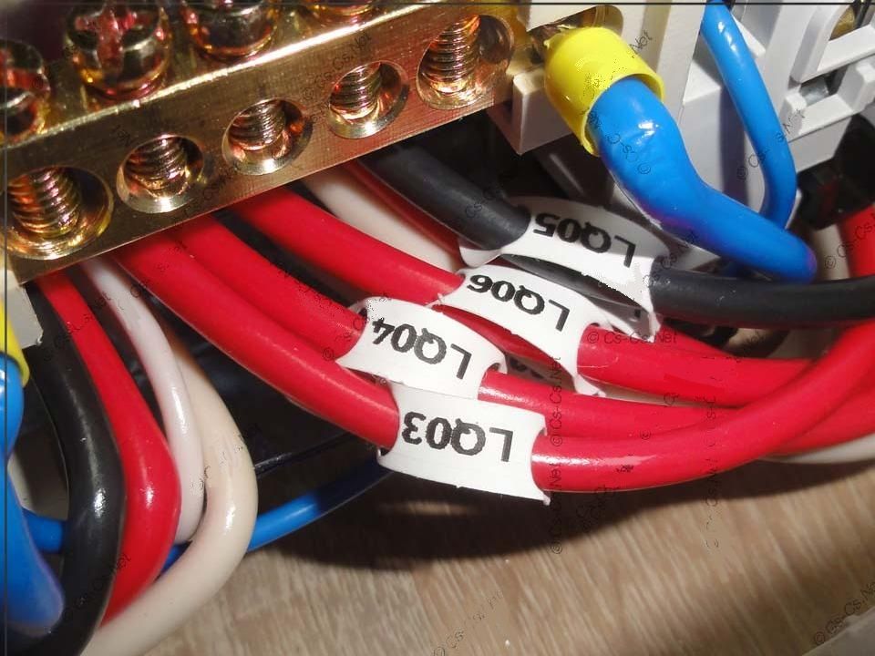
Markings on wires
For self-assembly you need to have a shield minimum set.
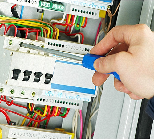
When fixing conductors and busbars, it is necessary to use quality screwdrivers– if the edges are knocked down, then the terminal bolts may be damaged, after which it will be impossible to unscrew them. Holding the wire with one hand, you need to clamp it in the terminal clamp, and then press it.
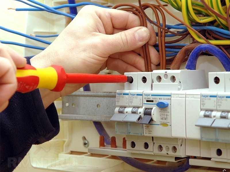
Wires held by hand are fixed in the terminal clamp
To do this, you need to grasp the stop with your whole body, applying force along the axis of the screwdriver, while simultaneously turning it. This will prevent the screwdriver from slipping and damaging the edges of the terminal bolts.
It is necessary to tighten the bolts until the wires are completely fixed, overcoming elastic resistance. It is important not to overdo it here, so as not to damage the modular machines or the panel body.
Pressing the wire into the module terminal clamp
If electricity is supplied to the input circuit breaker of the panel, and the final recipients of electricity are connected - sockets and switches along with distribution boxes, then you can check the correct installation after connecting each module and wiring line, turning on the input and, and checking the functionality of the final sockets and lighting fixtures.
If everything works, the machine does not knock out, and there is no characteristic smell of burnt insulation, the input machine must be turned off, continuing installation, proceed to connecting the next machine.
During the assembly process, the machines also need to be marked according to the connected consumer groups.
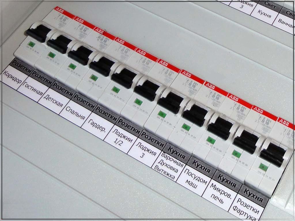
Marking of circuit breakers
Thus, dividing the process of installing the panel into stages, monitoring the performance of each connection during operation, you can do it yourself assemble a shield of any complexity without resorting to the services of professional electricians.
Complex electrical panel
Checking and preventing the shield
After assembling the shield, the machines must be “loaded”, that is, allowed to work with a load close to the nominal one. If somewhere the wires are fastened poorly, then sparking will be observed in this place, or the terminal itself and the module will become very hot. In this case, the under-tightened terminal will need to be tightened.
If any of the modules gets very hot, you should check the calculations - perhaps the machine was selected incorrectly, or the load is too large. There are often cases of counterfeits hitting the market, which will overheat during loading and break down under a load that does not correspond to the nominal value.
Therefore, even if the installation is carried out in accordance with all the rules and regulations, it is imperative to verify the reliable operation of the panel by loading the installed machines and observing their operation for several hours.
After this check, installation is complete. For repair and modernization in the future on the shield cover, or in any convenient place you need to attach the electrical diagram.
Connection diagram on the switchboard door
Need to check periodically condition of the equipment and tighten the fastening bolts due to loss of elasticity in the fixed conductors due to the fluidity of the metal.
Good day to all readers. Today there will be a second “master class”. The first one was by .
Today we will talk about installing a switchboard. Let me briefly remind you about color coding wires Blue is always the neutral working conductor, yellow-green is always the grounding protective conductor.

In general, the technology differs little from installation distribution boxes. All cables are inserted into the shield, and then the shield is securely fastened. Next, a small cut is made on each cable and, stretching the cable cores in different directions, we break the general insulation until the cable enters the shield. At the top of the shield you can see the corrugation. There are not always enough holes in the shield to insert the required number of cables. Then the required hole is cut out with a grinder and the edges are protected either with rubber seals or, as in my case, with corrugation around the entire perimeter of the hole. 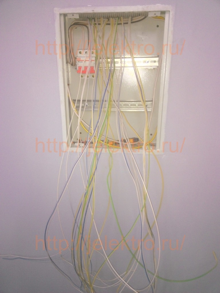
Carefully cut off the insulation. 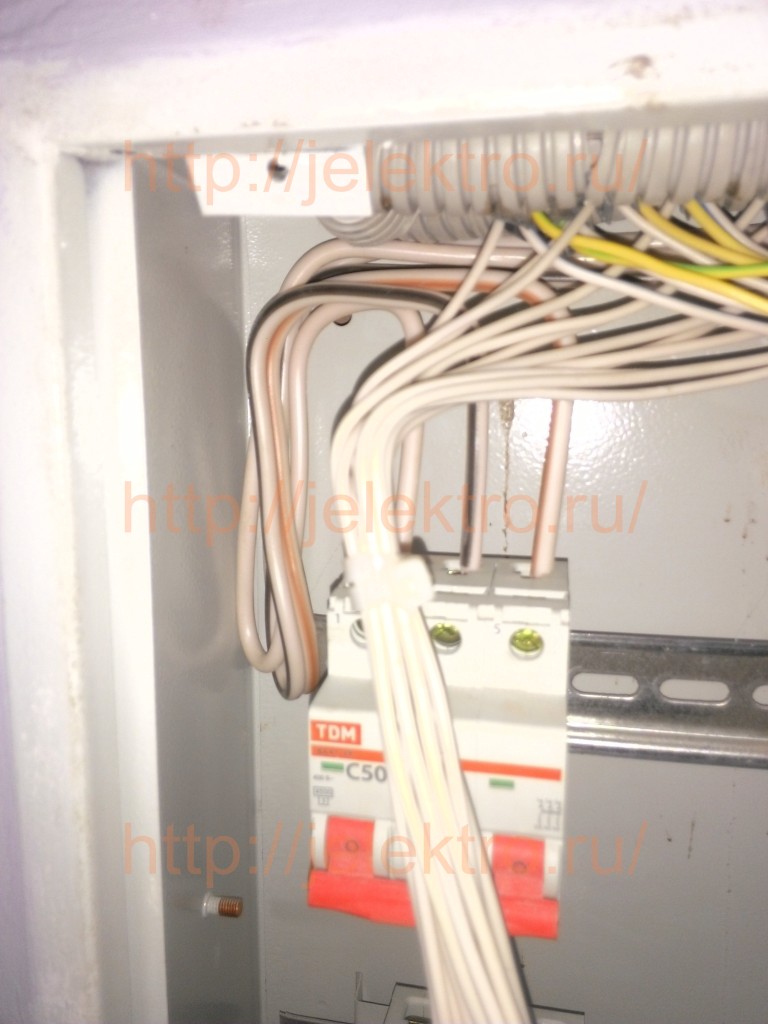
A little earlier I did the same situation with the power cable. It is also clear that he did not put the wires into the machine immediately, but made a reserve. If it is possible to replace the wire, then you don’t have to do it, but still, I strongly recommend that you always do it. It is much easier to shorten the core and clamp it again than to change the entire cable or restore the insulation either with heat-shrink tube or electrical tape, and this is in the best case, in the worst case, if the core burns off, you can safely start a new repair. 
If you have already signed the cable, then all that remains is to mark it according to the circuit diagram for connecting the machines. In this case, this is cable number 7, which will go to the seventh machine (the input machine, when I mark the wires, I don’t count. If the cable is not signed, then first find the necessary lines, sign them, then remove the insulation and immediately mark the ends of the wires.
You can sign on insulation using a marker (they are available in different colors, including white, but I use regular black permanent). There are also other methods: self-adhesive tags, plastic tags in the form of a nylon clamp, in the form of typed tags. If there are a lot of cables going into the shield, then it makes sense to spend money on them. In this case, I did without them. 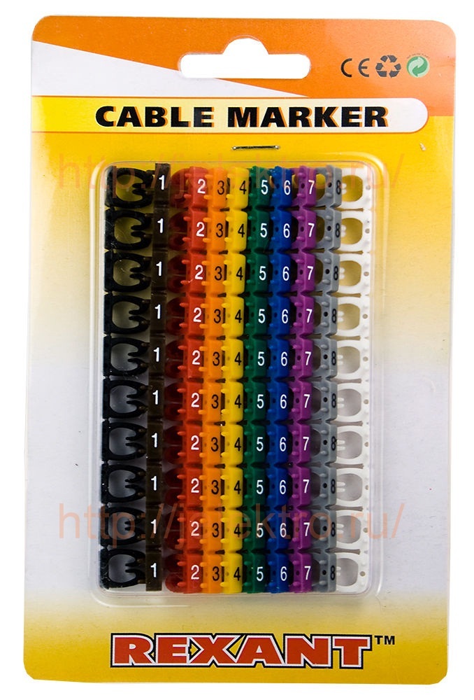


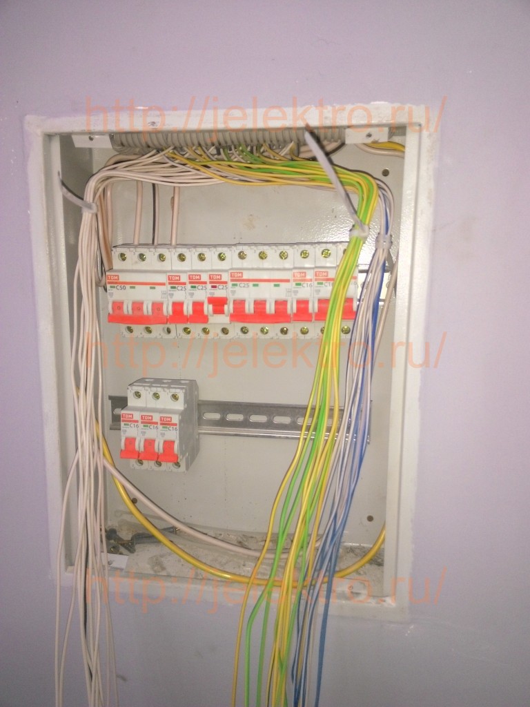
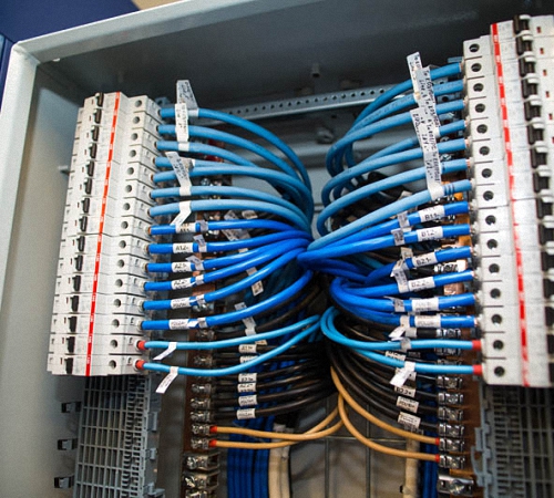
After the cores of all the cables are marked, we collect them into three bundles and separate them in different directions: all phase conductors in one direction, all neutral and ground conductors in the other. We fasten them with nylon clamps, which are usually called zip ties. A little science: if you purchased a package of fragile and brittle zip ties at the store, but you don’t really want to return to the store, just soak the ties in water overnight. Of course, they will not have the same strength, but they will no longer break. 
Now we separate the cores “by floor” and also fasten them with ties. 
Now we arrange all the machines and prepare the jumpers. 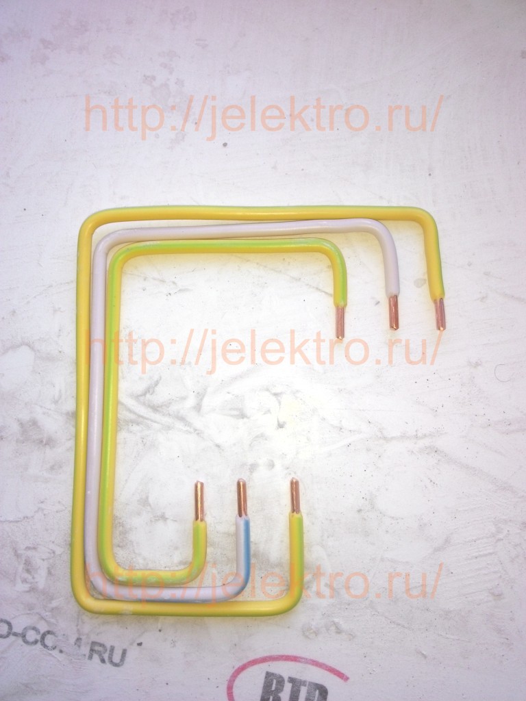
These are jumpers from the input machine to the “ground floor”. Let me remind you that power to the machine must be supplied to the upper terminals and removed from the lower ones. Of course, it’s not too critical if you do the opposite, but there may be nuances. The upper contacts are motionless, therefore, if suddenly the lower contact received some kind of damage inside, then it will in any case be disconnected from the upper contact, but if voltage comes to the lower contact, we assume it fell apart and shorted the neighboring one. Not the most pleasant situation and consequences. So it’s better not to tempt fate and supply power to the upper terminals of the machines.
Jumpers must be made based on the planned power and the input circuit breaker, in this case the circuit breaker is 50 amperes, and this is a wire with a cross-section of 10 mm2. Therefore, all jumpers must be made with this wire. If you decide to clamp two wires of different cross-sections in one terminal, then you must first either terminate them, twist them, or come up with something else, because a thicker wire will not allow you to clamp a thinner one. 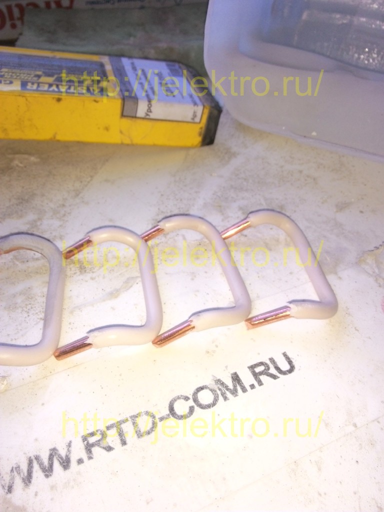
As you know, in three-phase network There are three phases: “A”, “B” and “C”. I bend the jumpers going to phases “A” and “C” in a similar way. 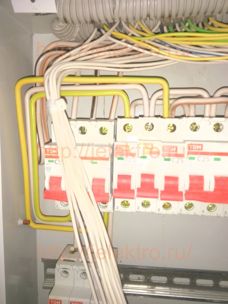
This photo shows why I do this. The “A” phase jumpers are placed inside the panel, the “C” phase jumpers are placed outside, and the “B” phase jumpers simply go in the middle of the terminal group of the machines. 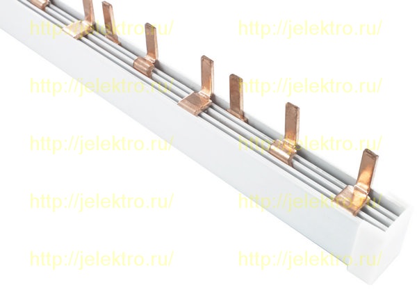
An electric distribution comb can also be used for this purpose. But besides all the advantages, it has two disadvantages. In order to replace the machine in the future, you will have to loosen the fastening of all the machines, otherwise the faulty machine will not be removed. And secondly, it is not suitable for RCDs and automatic devices. 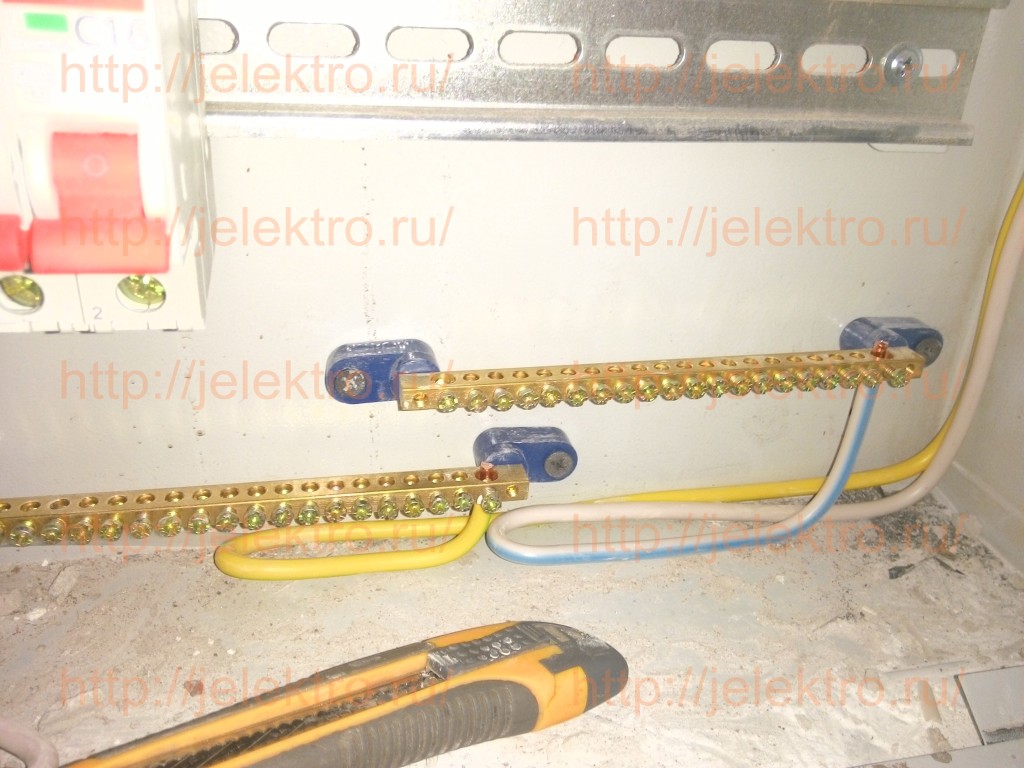
Now we install the grounding bars and the working neutral. As you can see, a small reserve has also been made. The busbars can also be mounted on a DIN rail, but it is not always convenient to install the wires later (there are shields with very little space), so in this case I simply took insulated busbars on fastenings and secured them to the back wall with ordinary self-tapping screws. 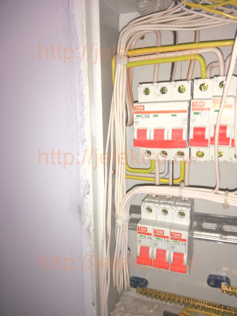
Well, now let's proceed directly to connecting the wires. We make a small reserve, lay it down and tighten it with clamps. 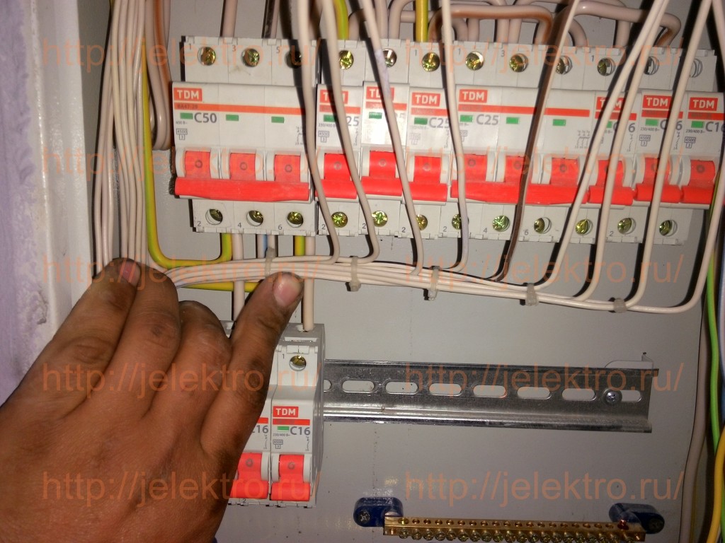
Since the cable wires are pre-marked, just take the one you need and bend it under the terminal of the machine, tightening two or three wires with clamps so that your entire structure is held in place. 
Use a marker to mark the wire cut. 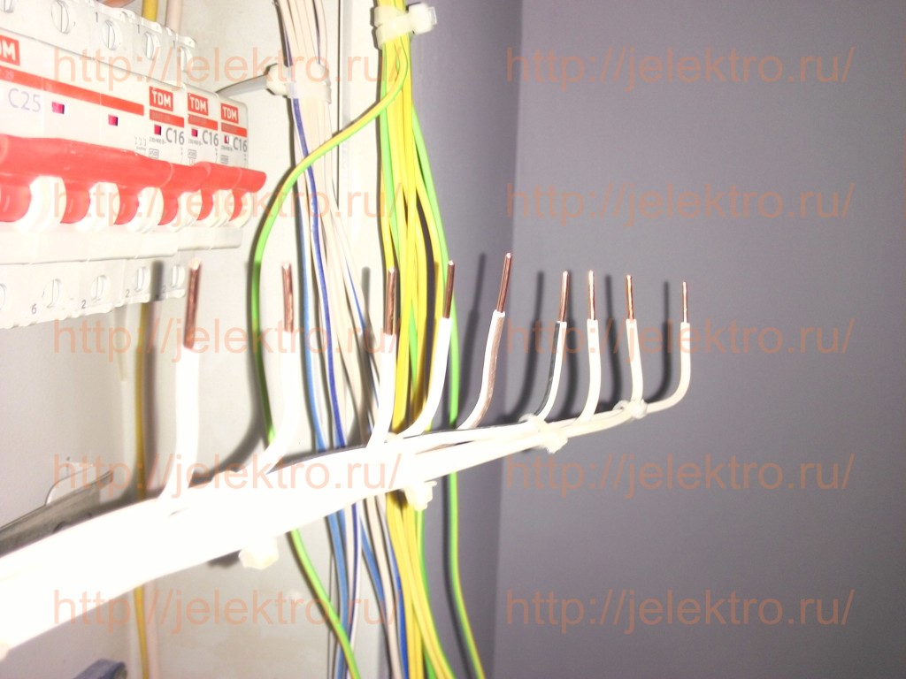
Bite off the excess length of the wire and... 
All that remains is to insert the wires into the terminals of the machines and tighten them properly. Please contact close attention so that the wire goes directly into the clamp. Very often the wire ends up behind the clamp. You seem to have tightened it, but in fact, the wire is not clamped. Also pay attention that it is the core that is clamped so that the insulation does not get into the clamp. At a minimum, there will be no contact, at a maximum, the contact will be weak, over time it will heat up and either the machine will fail or the wire will burn out. 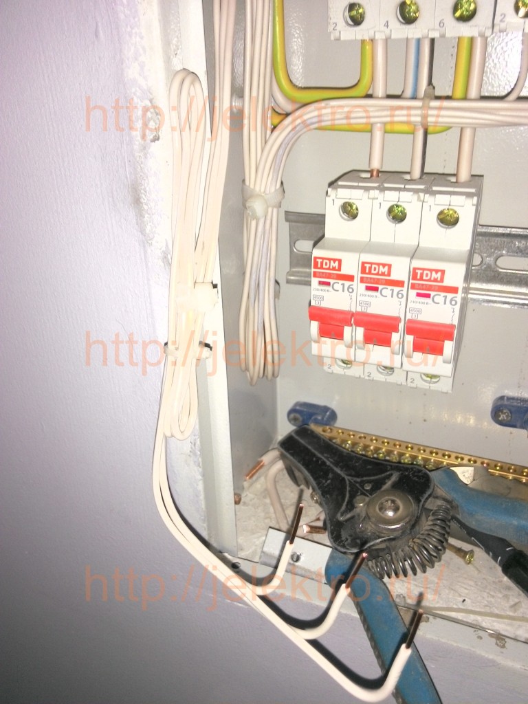
We perform exactly the same manipulations with the “second floor”. 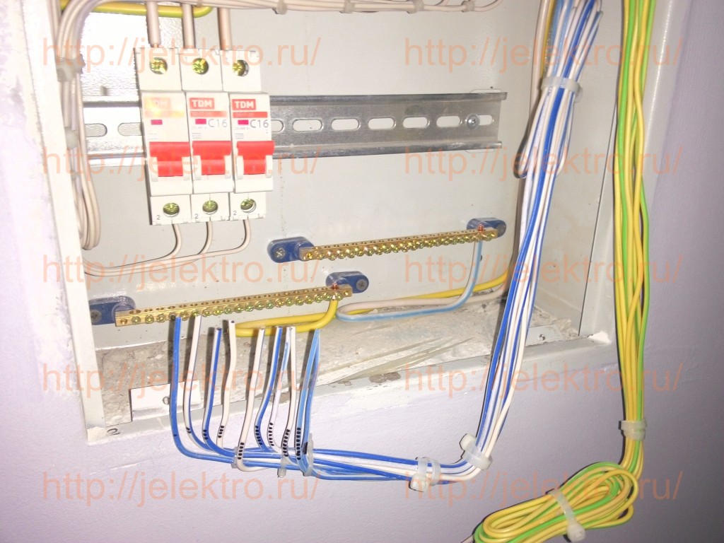
We do the same with zero working conductors. Please note that they also come in order, according to the machines. 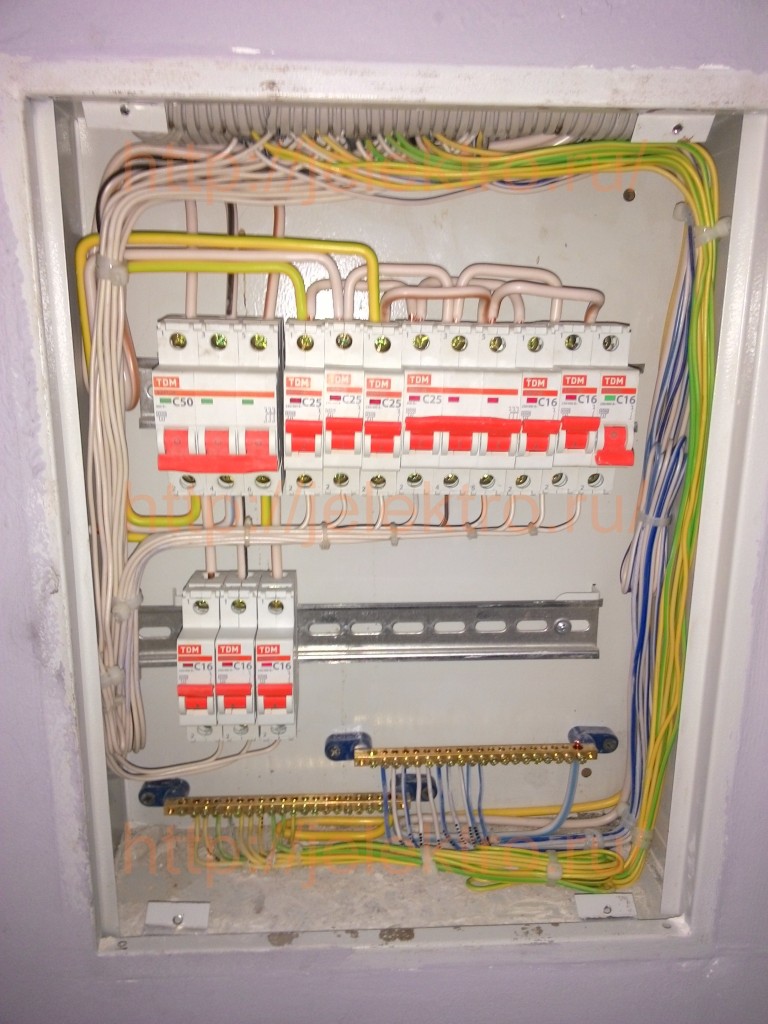
We do the same with grounding. Now, having turned off the first machine, if we need to disconnect the line, we don’t have to think: “Where is the zero or ground from this line?..” - because on the zero working and grounding buses these are also the first wires. You will also not need to look for the neutral or grounding wires of any line in case of any doubts or malfunctions. So, our shield is almost ready. All that remains is to install the jumper from the grounding busbar onto the body of the switchboard (if it is metal and this is provided by the manufacturer, if it is not provided, but the shield is metal, then we drill a hole and install the jumper ourselves) and the jumper on the switchboard door. If this is an input switchboard, that is, it receives power from the street and grounding, then we must install a jumper between the busbars. In the photo, a five-core cable from the ASU, in which this jumper is already installed, is inserted into the shield. Read more about this in articles on.
I usually tighten the terminals with a screwdriver. I set the ratchet to maximum. This way you don’t tear off the head of the screw with a screwdriver and you tighten the wire quite well, so that later you can calmly work on other wires, but after the installation is complete, I take a screwdriver and pull everything out properly by hand. Electricity does not like weak contact.
We number the machines. This is always done from left to right and from top to bottom, regardless of where the incoming machine is located (specifically on this panel it is located at the top right, and the introductory RCD, which goes immediately after the machine at number “8”, and from the RCD the lines go to all other machines).
We sign the machines on the door, either print a sheet and glue it, or use a marker.
That's all. If you did everything as written in the article, you will get a competent, safe and beautiful one. All the best to you.
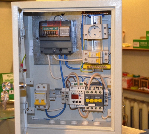
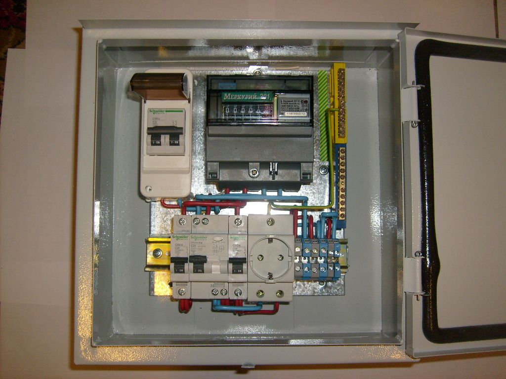
In a modern house, be it a city apartment or country house, there are a large number of electrical appliances. For their continuous and safe operation, a device is required that distributes and controls incoming energy from the network. electrical energy. Such a device is an electrical panel. The installation of the electrical panel can be done with the help of specialist electricians, or you can do it yourself.
The electrical panel is a housing in which, as a rule, the following electrical devices are mounted:
- electric energy meter;
- main circuit breaker;
- residual current device ();
- automatic switching off of consumer lines;
- distribution bus;
- zero bus;
- ground bus.
The panel body is a metal or plastic box with a lid, which is installed on the wall and contains all the listed electrical appliances.
An electricity meter is designed to determine the amount of electricity consumed. It can be installed by employees of the energy network company or independently. In the latter case, it must be sealed by the energy company.
The main power switch is designed to completely cut off power to the panel. Typically this switch is two-pole and cuts off both wires supplying electricity. Both phase and zero. Its power must correspond to the total power of all electricity consumers connected in the apartment or house.
Most often, circuit breakers with a rated current of 32 A are used as input switches.
A residual current device is a device that, using a differential transformer, evaluates the balance between incoming and outgoing currents. In the event of an imbalance of currents, and this can happen when a person comes under voltage or uncontrolled current leaks, the RCD turns off the network. usually calculated on the leakage current, which is considered safe for humans and is 30 -100 mA.
Switching off individual lines is designed to protect and disconnect a group of consumers or individual powerful devices. For example, a water heater or washing machine. As a rule, they are designed for a current of 16 A. These machines are single-pole.
The distribution bus is a copper strip with which the input contacts of line switching machines are connected.
The zero bus is a block with terminals to which all neutral wires coming from consumers are connected.
The grounding bus is designed to connect grounding wires.
Do-it-yourself electrical panel installation - what to install where?
Before assembling the electrical panel with your own hands, you need to remember that working with circuits high voltage poses a danger to life. Therefore, it is imperative to follow the rules related to electrical safety.
The basic rule for assembling electrical panels is that you can only work when the electrical wiring is disconnected. In order to make sure that there is no voltage on the elements of the electrical panel, you can use indicator screwdriver. And only as a last resort can you work in the presence of voltage, but be sure to use special dielectric gloves.
- Selection and installation of the shield housing.
- Electric meter connection.
When choosing an electrical panel housing, it is advisable to choose a plastic housing. The type of housing also depends on the type. In the case of open wiring, the housing is mounted mounted, when it is installed directly on the wall at a height of about one and a half meters. Subject to availability hidden wiring it is necessary to make a special niche in the wall. The housing is attached to the wall using self-tapping screws or screws with dowels.
In any case, the installation diagram of the electrical panel provides for free access to it.
According to the unspoken rules of network companies, in order to prevent the theft of electricity, the electricity meter must be connected directly to the network input. Its installation is usually carried out by a network company. If necessary, you can implement it yourself. This device has 4 terminals:
- the input phase wire coming from external network;
- the phase wire going into the house to electricity consumers is connected to terminal No. 2;
- the input neutral wire coming from the external network is connected to terminal No. 3;
- The neutral wire is connected to terminal No. 4, which goes into the house to electricity consumers.
Special DIN strips are usually provided for installation in the panel. There are usually three of them - two short and one long. The main network switch and RCD are installed on short strips. Automatic switches for individual lines are installed on a long strip. Using the distribution bus, the inputs of the line switching machines are connected to each other. To do this, the terminals are unscrewed and the bent ends of the bus are inserted into them, after which the terminals are wrapped.
For installation on DIN strips, automatic devices and RCDs have special clamps that securely fasten these devices.
Using self-tapping screws, a zero bus and a ground bus are installed in the electrical panel housing.
Electrical panel connection diagram - connect the wires
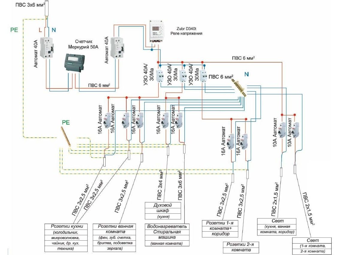
The phase and neutral wires of the external network are connected to the corresponding terminals of the meter. From the output terminals of the meter they go to the terminals of the main switch, and the output phase and zero terminals of the main switch are connected to the input terminals of the RCD. The output phase terminal of the residual current device is connected by a wire to the terminal of one of the individual line circuit breakers connected by the distribution bus, and the output zero terminal of the RCD is connected to one of the terminals of the zero bus. ![]()
The phase wires of each individual consumer line are connected to the output terminal of their machine, and the neutral wire of the line is connected to the neutral bus of the panel.
The presence of a grounding bus in the electrical panel complies with modern safety regulations. This bus must be connected to the house's grounding system.
Accordingly, wiring in a house that meets modern safety rules must consist of a three-wire wire, including phase, neutral and ground lines.
When installing an electrical panel, it is advisable to follow the following rules:
- observe safety and try to work only when the network is turned off;
- when connecting wires, their ends must be used with special crimps;
- When connecting equipment, you must pay attention to ensuring good contacts. If there are weak contacts, the housing and insulation may heat up and melt, which can lead to a short circuit;
- To facilitate line recognition during repairs, it is necessary to mark the wires when installing the electrical panel.
Do-it-yourself electrical panel assembly on video