The article is intended for the average developer who is puzzled by age-old questions: where to start with this complex and incomprehensible electrician, how it will all happen, when you can start, where to look, who to invite...
Arrangement of electrical communications is the most important stage in the construction of a private house. It is absolutely obvious that you cannot begin installing electrical wiring without detailed design, and this statement applies not only to buildings under construction, but also to those undergoing reconstruction and major repairs. Not only the functionality of all energy-dependent devices and household appliances, but also the safety of people depends on the quality of planning and execution of electrical installation work. The owner, like no one else, is interested in thorough preparation, so it is not worth saving either time or money here.
The most optimal solution, of course, would be to order a project from a specialized organization, especially since well-developed documentation will help you calmly conduct a conversation with Rostechnadzor and business entities and put the facility into operation. The power supply project is the only document on which electrical installation can be carried out; its main purpose is to ensure the safety and efficiency of wiring already at the development stage. In fact, this is a whole package of documents containing the full amount of necessary information:
- wiring diagrams, conductor characteristics;
- installation methods and types of connection of all elements;
- indication of all equipment, consumer specifications;
- location and features of electrical installation products;
- load calculations...
Even if the owner of the home turns to professionals, he must provide the engineers with technical specifications, which means he must first understand many issues on his own. Now we will not try to make an “official” electrical project for a country house on our own, but we will try to outline all the main points, the systematization of which will help you:
- competently answer questions from designers;
- calculate the required power, redistribute limited energy resources;
- plan the order of electrical installation work and synchronize it with general construction work;
- predict your expenses;
- competently inspect hired specialists, or get to work yourself.
In general, our task is to completely eliminate the possibility of unpleasant surprises and keep everything under control in any situation.
Technical specifications - the starting point of design
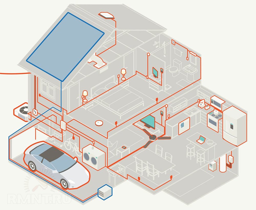
Conventionally, the power supply of a country house is divided into three main parts: wiring in a residential building, organizing communications on the street, connecting outbuildings. Each of these areas should be considered separately and have its own electrical circuit and working drawings. To solve this problem, you need to set yourself (or the designers) a technical task. This is the original plan, which shows all the power consumers of the house and outbuildings, lighting devices, and simplified communication routes. As a rule, the preparation of technical specifications is the result of the joint work of the designer, the customer and the contractor performing electrical installation work.
Drawing up technical specifications and a project for it will allow:
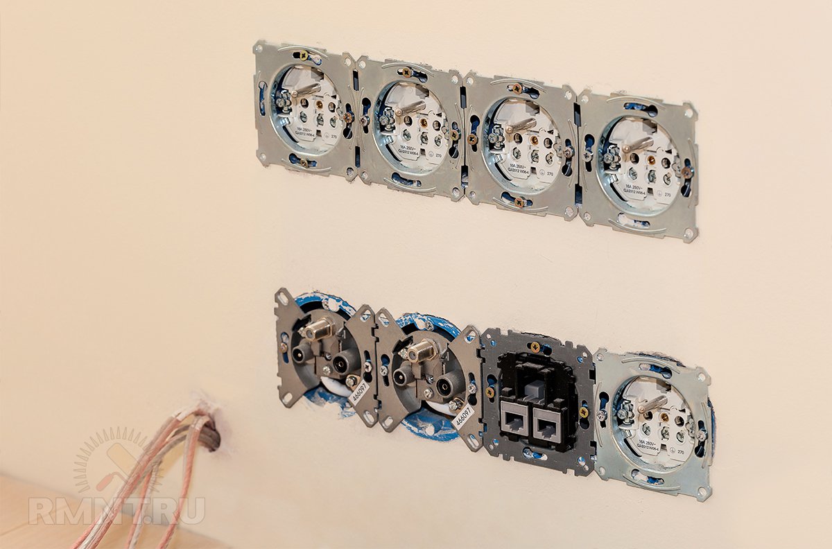
- take into account all points of electrical outlets so that every household appliance or unit is powered;
- arrange sockets and switches in places convenient for use, and distribution boxes in places accessible for maintenance;
- calculate the total power consumption.
We need to first create separate drawings of each floor of the house and each room, which schematically shows all the partitions, door blocks with the direction of opening of the leaf, furniture elements, large stationary appliances (TVs, computer, electric fireplace, refrigerator, internal units of split systems, boiler, jacuzzi etc.). A prerequisite is the connection of consumers to the enclosing structures, so you should either complete the construction of internal partitions, or make an accurate and final marking of the layout directly at the site, and determine the level of the finished floor. Only after this can we take measurements and make complete floor plans, where we will mark all the terminals, each socket, switch, and lamp.
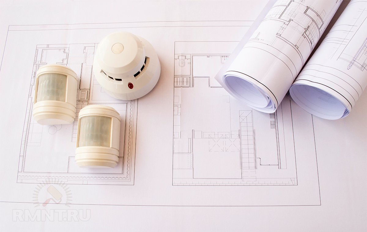
Special attention is paid to low-current networks - high-frequency TV, Internet, video surveillance, motion and presence sensors, stationary audio systems.
In some cases, local drawings are made for particularly stressed design and electrical components (specific walls, multi-level ceilings in individual rooms).
A very important point. To correctly draw up the technical specifications, it is necessary to have passports of all the main consumers; this is the only way to obtain reliable information about the dimensions of the products, methods of their connection, power, etc. For example, it is worth knowing in advance how many switching positions the chandelier in the living room will have (determines the number of wires conductor), or, for example, the specification of the hob (determines the cable cross-section, type and location of the terminal).
At this stage, it is necessary to take care not only of internal communications. We must not forget about: pumping stations; cleaning, air conditioning, ventilation systems; street lighting and outdoor sockets; anti-icing systems for gutters, steps; control and automation systems; backup/autonomous power supply.
When all consumers are known, the total load is calculated by simply summing the capacities. If the allocated energy resources are not enough, it is necessary to reconsider the equipment of the house and select more economical appliances. As a last resort, you can continue to develop the project and, based on it, request a larger limit from the electricity supplier.
Based on the technical specifications, you can make a list of necessary sockets, switches, and multi-gang frames. We recommend creating a general list by type of product, and several small lists to complete each room.
Let us note once again that the technical specifications cannot be drawn up while sitting at the table; more than half of this work is done by the homeowner “in the field” - with a tape measure in his hands, and the whole family behind his shoulder.
Making a schematic diagram of power supply
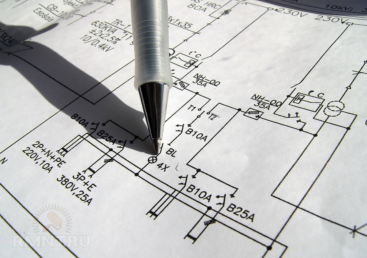
The schematic diagram is a very important and very complex part of the project, which is developed by specialists from electrical laboratories. This document is fundamental when planning and carrying out electrical installation work and when drawing up working drawings.
Our task is to create a simplified power supply diagram that will help us see the overall picture of the power supply at home. In fact, it can be a visual drawing, a drawing with symbols that will resemble a tree with a root in the form of a main distribution board and branches ending in individual sockets or lamps. The trunk is the highway, where the branches are separated - these will be additional panels or distribution (socket) boxes. Cables running directly from the switchboard to the device may be knocked out of the common outline. You can include circuit breakers and residual current devices in the circuit, then it will look something like this:
If the home's electrical system is very complex, then it makes sense to make a diagram of the power circuits and your own circuit for lighting, since they are always wired separately in the house.
If the cottage has three-phase power supply, then we make three different circuits. At the same time, in order to achieve power balance, based on the technical specifications (consumer power), the load should be evenly distributed on each of the phases - the devices and units should be grouped proportionally.
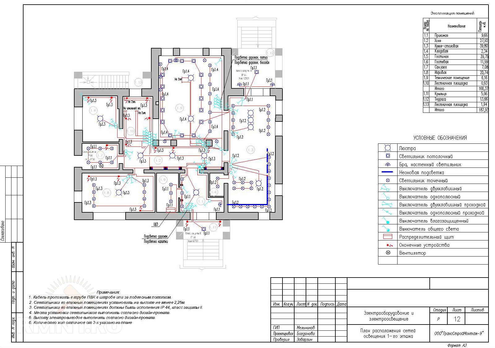
We make working drawings
A working drawing is a document used by an on-site electrician to lay out cables. If the project is more focused on justifying the choice and coordination of certain technical solutions, then the working documents are intended for the implementation of this project. This is a hybrid of technical specification drawings and a circuit diagram. The working drawing is developed on the basis of the technical design and in strict compliance with the requirements of the PUE.
Here you need maximum detail for each room; sometimes they create their own working drawing for a specific wall. Separately, it is necessary to depict a working floor plan, which shows the highways and entries into specific rooms.
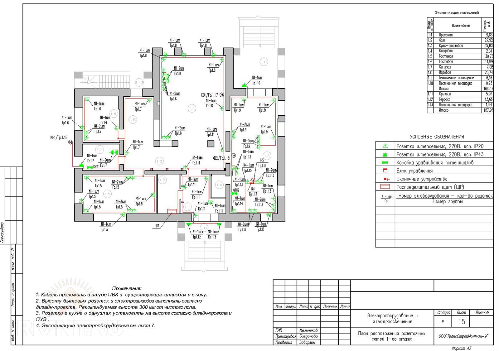
What should be indicated in the drawing:
- Output points linked to walls, floors, ceilings; single and multi-point sockets; switches, lamps.
- The lines indicate which lighting groups a specific switch key is responsible for.
- Locations of distribution boxes and main points, group panels.
- Wire routes.
- Brand and cross-section of conductors.
- Connecting a group to one phase or another.
- Arrangement of low-current circuits.
Don’t forget to give the exact name to the room or unit for which the plan was made.
When making a working drawing, use color highlighting, mark groups and individual consumers with numbers, make notes and explanations. Network lines are drawn on the plan with thicker lines than for drawing building elements and stationary equipment. The number of conductors in one line is indicated by short inclined strokes-serifs directly on it. There is a generally accepted set of symbols, as well as established requirements for numbers and inscriptions used in electrical drawings. They are displayed in GOST 21.614-88.
Determining cable routing methods
Depending on the building design and types of finishing, it is necessary to decide on the methods of laying cables. For a private home, there are two main options:
- by gender
- along the ceiling
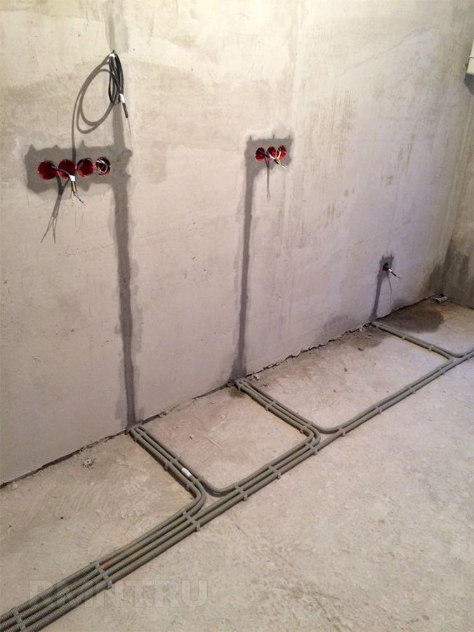
Wiring in the floor is possible if the screed has not yet been poured. The method has a number of advantages, including more economical cable consumption. Installation on the ceiling is possible if suspended structures are used. This wiring option allows for safe drilling of floors during future general construction work and makes it possible to carry out installation regardless of the type and condition of the floor. For wooden houses, open wiring is often used in channels or on insulators, including along walls.

To select the route for each line, you must:
- carry out a thorough inspection of the structure and technical condition of the building;
- plan ways to bypass/cross obstacles and technical communications;
- develop ways to move to different rooms/floors/outside.
Counting the power cable
Now that we have the exact location and specifics of electrical points, the communication routes have been determined, a decision has been made on the installation method, we have a schematic diagram and a working drawing (which means we know where the distribution boxes will be and which consumers are powered by them) — we can accurately calculate the required quantity of each type of cable.

In a private house there must be grounding - therefore it is necessary to use a three-core wire with a soft copper conductor in double insulation. For sockets, wires with a core cross-section of 2.5 mm 2 are suitable, 1.5 squares are used for lighting, for powerful consumers (with connection to terminals) and for powering intermediate switchboards (storey panels, for individual buildings), cables of 4 mm 2 or even are often used by 6 mm 2. Note that the following consumers are traditionally connected directly to the switchboards, bypassing the boxes:
- engineering units and systems (pumping stations, air conditioners, heated floors, cleaning and anti-icing systems);
- powerful household appliances (oven, hob, boiler, washing machine, dishwasher, electric boilers and heaters).
Using a tape measure, measure the length of each conductor:
- from the shield to the junction box;
- from the switchboard to the consumer (with direct connection);
- from the box to the power consumer, to the switch, to the lighting device.

You should take into account the supply of wire for output from walls and junction boxes - from 15 to 25 cm, and the supply of wire near the electrical panel - up to 1 meter (if there is a large number of wires, some of them have to be run into the box from below, and some from above).
We make a list of all the wires for each room, give the name of the group or device in numbers, and designate them in accordance with the markings indicated in the working design. The work seems unnecessary and tedious, but it will still have to be done at the stage of preparing and laying cables.
Summing up the indicators, we get the need for cables and wires of various types. The same figures show how much protective corrugation, insulating pipes or cable ducts will need to be purchased.
Planning a distribution board
As we have already said, in a private house there can be several panels, this is the main input and distribution device, as well as simplified panels for floors and auxiliary buildings. Each of them is assembled according to approximately the same principle and contains a similar set of elements.
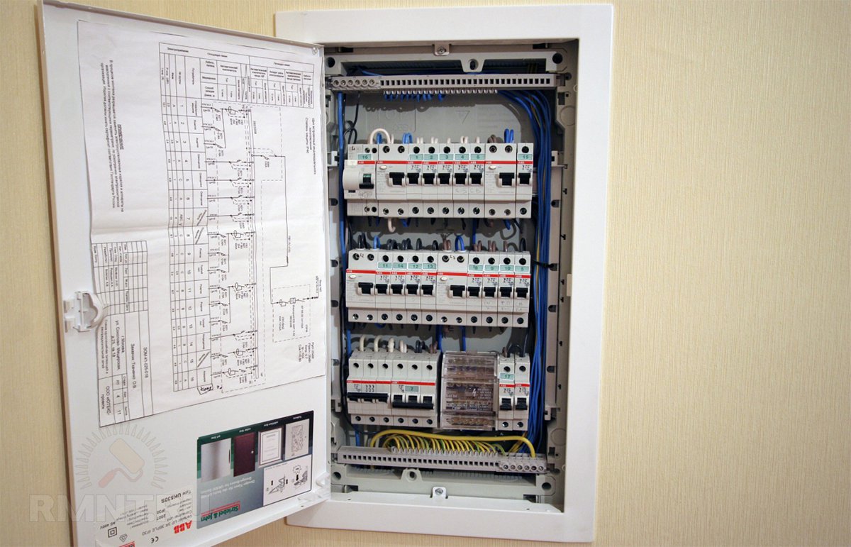
The number of installation products here can be very diverse, but you should always give preference to boxes with several spare “places”.
To ensure high-quality installation of shields, their design should be carefully considered. For this purpose, a special wiring diagram is created for each input distribution device. The procedure is as follows:
- We make a list of all incoming wires.
- We indicate the load and maximum current for each of them.
- We select a circuit breaker that corresponds to the characteristics of all items in the list.
- We select residual current devices for several groups of consumers, but a fire protection RCD is installed on the entire system.
- We make a working drawing.
- We make a list of necessary protection devices and components.
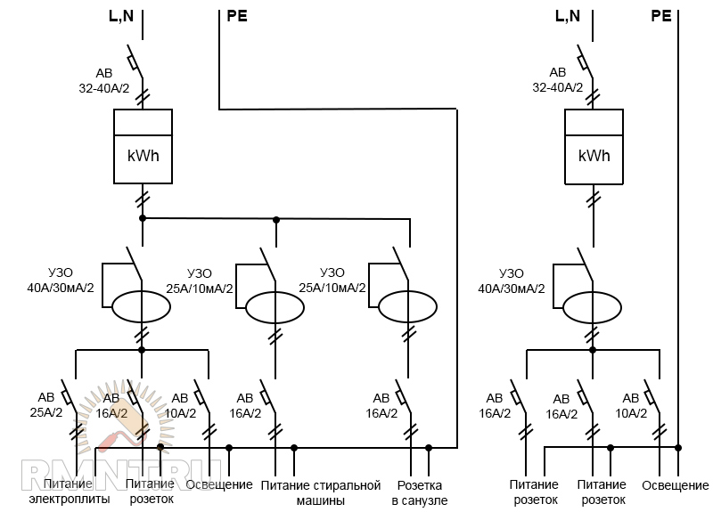
Examples of electrical panel diagrams:
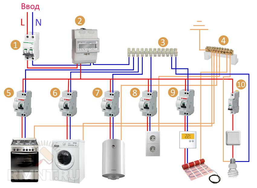 1—introductory machine; 2 - counter; 3 - zero bus; 4 - grounding bus; 5-9 - differential automatic machines; 10 - automatic lighting
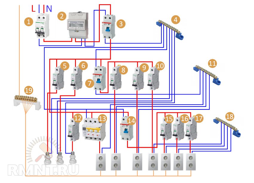 1—introductory machine; 2 - counter; 3 - fire protection RCD; 4 - common zero bus; 5, 6, 12 — automatic devices for lighting; 7 - RCD for consumers 2, 3, 4; 8, 9, 10 — machines for consumers 2, 3, 4; 11 - additional zero bus; 13 — differential automatic; 14 - RCD for circuits 5, 6, 7; 15, 16, 17 — machines for consumers 5, 6, 7; 18 - additional zero bus; 19 - ground bus (conductors from lighting can also come here)
Attention! Switching of low-current networks cannot be done in power panels; separate boxes must be used for them.
We are planning the installation of electrical wiring
The main task of this stage is to coordinate the arrangement of power supply with other construction work. The second point is to logically organize the activities of the installer; optimize the processes of supplying materials, using special tools and devices; properly prepare the workplace.
Electrical installation work begins at the stage of rough general construction operations, usually in parallel with them. For example, cable routing along the floor is carried out before installing screeds, but on walls that are being plastered, it would be more rational to finish the rough finish, cut the grooves, then run the wires and fix the socket boxes. When covering walls and ceilings using frames, the cables are routed before installation of the cladding and remain in the cavity, and then holes are cut for the installation boxes and the ends are pulled out. Open wiring is done over finishing trims. The mechanisms of electrical installation products are installed after the main painting and cladding work; frames of sockets and switches, lighting fixtures are installed after finishing.

Electrical installation work is the least mechanized in construction, but some aspects can be optimized. For example, you can order a factory-made complete input distribution device, carry out a series of preparatory works in advance (marking, cutting and marking cables, pulling conductors into a protective corrugation, making grooves, installing line fastening elements in place, installing installation boxes, stripping and crimping ends). Many of these jobs can be done by less qualified personnel.
In capital construction, measured pieces of wires from one box are switched on a special preparation line, and then they are pulled to the installation boxes (nodal method). The second option is “beam”, when an electrical installation product is connected to a prepared wire (cut, stripped and crimped) on a stand, and then the cable is pulled to the junction box. In low-rise individual construction, due to the relatively small volume of work, these operations are not subject to industrialization, however, all of them must be carried out in accordance with current regulatory documents, such as PUE or SNiP 3.05.06-85 “Electrical devices”.

In a private house, manipulations to organize input will be mandatory. The developer raises a lot of questions regarding the arrangement of grounding. We list the stages of installation of the “interior” in chronological order (some operations can be performed simultaneously); for auxiliary buildings and street consumers, the order of their implementation does not change:
- Marking the locations of installation products and routes of lines.
- Cutting grooves and niches for installation and distribution boxes, preparing channels.
- Making passages to various rooms.
- Installation of boxes, socket boxes, boxes for ASU.
- Preparing cables for installation.
- Layout and fixation of power wires along their routes, marking of conductors.
- Installation of lighting circuits.
- Wiring of low-current networks.
- Preparation and switching of conductors in junction boxes.
- Assembly of distribution boards, switching.
- Checking the system's functionality.
- Installation of electrical installation mechanisms.
- Second check, commissioning.
- Installation of facades for sockets and switches.
- Installation and connection of lighting devices, household appliances.
- Connection of various power units, autonomous power supply devices and automatic transfer switches.
- Connecting low-current consumers (antennas, fire and security sensors, routers and modems, audio system elements).
This is how we saw the planning of work on the design and installation of electrical networks for a country house. Of course, we were not able to cover all the nuances, but we hope that you were able to glean some useful information. In subsequent publications we will continue the “electric” theme.