Of the entire range of currently produced electric motors, the most widely used is the three-phase asynchronous motor. Almost half of the world's electricity is used by these machines. They are widely used in the metalworking and woodworking industries. An asynchronous motor is indispensable in factories and pumping stations. You cannot do without such machines in everyday life, where they are used in other household appliances and in hand-held power tools.
The scope of application of these electric machines is expanding every day, as both the models themselves and the materials used for their manufacture are being improved.
What are the main parts of this machine?
Having disassembled a three-phase asynchronous motor, you can observe two main elements.
1. Stator.
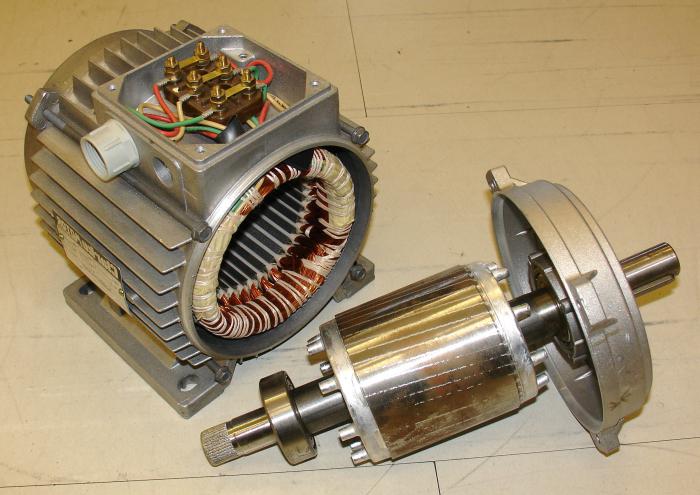
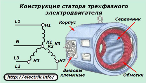
One of the most important details is stator.In the photo above this part of the engine is located on the left. It consists of the following main elements:
1. Frame. It is necessary to connect all parts of the machine. If the engine is small, then the housing is made of one piece. The material used is cast iron. Steel or aluminum alloys are also used. Sometimes the housing of small engines combines the functions of the core. If the engine has large sizes and power, then the body is welded from separate parts.
2. Core. This engine element is pressed into the housing. It serves to improve the quality of magnetic induction. The core is made of electrical steel plates. In order to reduce losses inevitable when eddy currents appear, each plate is coated with a layer of special varnish.
3. Winding. It is placed in the grooves of the core. Consists of coils of copper wire that are assembled into sections. Connected in a certain sequence, they form three coils, which together form the stator winding. It connects directly to the network, which is why it is called primary.
Rotor- this is the moving part of the engine. In the photo it is on the right. It serves to convert the force of magnetic fields into mechanical energy. The rotor of an asynchronous motor consists of the following parts:
1. Shaft. Bearings are attached to its shanks. They are pressed into shields that are bolted to the end walls of the stator box.
2. A core that is assembled on a shaft. Consists of special steel plates with such valuable property as low resistance to magnetic fields. The core, having the shape of a cylinder, is the basis for laying the armature winding. The rotor, or, as it is also called, the secondary winding receives energy thanks to the magnetic field that appears around the stator coils when electric current passes through them.
Engines by type of manufacturing of the moving part
The engines are distinguished:
1. Having a short-circuited rotor winding. One of the versions of this part is shown in the figure. 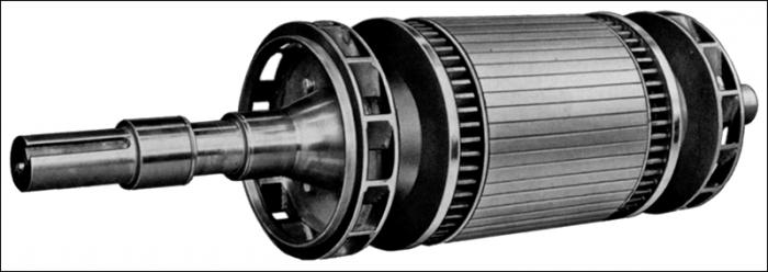
A squirrel-cage induction motor has a winding made of aluminum rods that are located in slots in the core. At the end part they are short-circuited with rings.
2. Electric motors having a rotor made with slip rings. 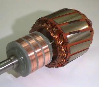
Both types asynchronous motors The stator design is the same. They differ only in the design of the anchor.
What is the working principle
The armature of a three-phase asynchronous motor, designed in a similar way, is driven into rotation due to the effect of the appearance of an alternating magnetic field in the stator coils. To understand how this happens, it is necessary to recall the physical law of self-induction. It states that a magnetic field arises around a conductor through which a flow of charged particles passes. Its value will be directly proportional to the inductance of the wire and the intensity of the flow of charged particles flowing in it. In addition, this magnetic field generates a force with a certain direction. It is this that interests us, since it is the reason for the rotation of the rotor. For efficient operation of the motor, it is necessary to have a powerful magnetic flux. It is created thanks to a special method of installing the primary winding.
It is known that the power source has alternating voltage. Consequently, the magnetic field around the stator will have the same characteristic, which directly depends on the change in current in the supply network. It is noteworthy that each phase is shifted relative to each other by 120˚.
What happens in the stator winding
Each phase of the power supply is connected to the corresponding stator coil, so the magnetic field arising around them will be shifted by 120˚. The power source has an alternating voltage, therefore, an alternating magnetic field will arise around the stator coils that the asynchronous motor has. The asynchronous motor circuit is assembled so that the magnetic field arising around the stator coils gradually changes and sequentially passes from one winding to another. This creates the effect of a rotating magnetic field. You can calculate its rotation frequency. It will be measured in revolutions per minute. Determined by the formula: n=60f/p, where f is the frequency AC in the connected network (Hz), p - corresponds to the number of pole pairs mounted on the stator.
How does a rotor work?
Now it is necessary to consider what processes occur in the secondary winding. An asynchronous motor with a squirrel-cage rotor has a design feature. The fact is that voltage is not supplied to its armature winding. It appears there due to magnetic induction coupling with the primary winding. Therefore, a process occurs that is the opposite of what was observed in the stator, in accordance with the law, which states that when crossing a conductor, and in our case this is a short-circuited rotor winding, a magnetic flux arises in it electric current. Where does the magnetic field come from? It appeared around the primary coil when connecting a three-phase power source.
Let's connect the stator and rotor. What will happen?
Thus, we have an asynchronous squirrel-cage motor with a rotor in the winding of which electric current passes. This will be the cause of the appearance of a magnetic field around the armature winding. However, the polarity of this flux will be different from that created by the stator. Accordingly, the force generated by it will counteract the one caused by the magnetic field of the primary winding. This will set the rotor in motion, since the secondary coil is assembled on it, and the armature shaft shanks are fixed in the motor housing on bearings.
Let us consider the situation of interaction of forces arising from the magnetic fields of the stator and rotor over time. We know that the magnetic field of the primary winding rotates and has a certain frequency. The force it creates will move at a similar speed. This will make the asynchronous motor work. And its rotor will rotate freely around its axis.
Sliding effect
The situation when the rotor's power flows seem to be repelled by the rotating magnetic field of the stator is called slip. It should be noted that the frequency of an asynchronous motor (n1) is always less than that with which the stator magnetic field moves. This can be explained this way. In order for a current to arise in the rotor winding, it must be crossed by a magnetic flux with a certain angular velocity. And therefore, the statement is true that the shaft rotation speed is greater than or equal to zero, but less than the intensity of movement of the stator magnetic field. The rotor has a rotation speed that depends on the friction force in the bearings, as well as on the amount of power taken from the rotor shaft. Therefore, it seems to lag behind the magnetic field of the stator. It is because of this that the frequency is called asynchronous.
Thus, the electrical energy from the supply source was converted into kinetic energy of the rotating shaft. The speed of its rotation is directly proportional to the frequency of the supply network current and the number of pairs of stator poles. To increase the armature rotation speed, frequency converters can be used. However, the operation of these devices must be coordinated with the number of pole pairs.
How to connect the motor to a power source
To start an asynchronous motor, it must be connected to the network three-phase current. The asynchronous motor circuit is assembled in two ways. The figure shows the connection diagram of the motor leads, in which the stator windings are assembled in a star manner.
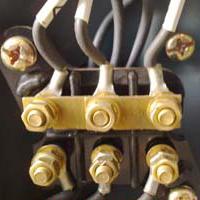
This figure shows another connection method called a "triangle". The circuits are assembled in a terminal box attached to the housing. 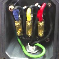
You should know that the beginnings of each of the three coils, they are also called phase windings, are called C1, C2, C3, respectively. The ends, which are named C4, C5, C6, are signed similarly. If there are no pin markings in the terminal box, then you will have to determine the beginnings and ends yourself.
How to reverse
If there is a need to start an asynchronous motor by changing the direction of rotation of the armature, you just need to swap the two wires of the connected three-phase voltage source.
Single-phase asynchronous motors
In everyday life, it is problematic to use three-phase motors due to the lack of the required voltage source. Therefore, there is a single-phase asynchronous motor. It also has a stator, but with a significant design difference. It lies in the number and method of arrangement of windings. This also determines the starting pattern of the machine.
If a single-phase asynchronous motor has a stator with two windings, then they will be located with a circumferential offset at an angle of 90˚. The coils are called starting and working. They are connected in parallel, but in order to create conditions for the appearance of a rotating magnetic field, an additional active resistance or capacitor is introduced. This creates a phase shift of the winding currents close to 90˚, which creates the conditions for the formation of a rotating magnetic field.
If the stator has only one coil, then a single-phase power source connected to it will cause a pulsating magnetic field. An alternating current will appear in the short-circuited rotor winding. It will cause the emergence of its own magnetic flux. The resultant of the two forces formed will be equal to zero. Therefore, to start an engine with this design, an additional push is required. You can create it by connecting capacitor circuit launch.
Connect the motor to a single-phase circuit
The electric motor, manufactured to operate from a three-phase power source, can also operate from a household single-phase network, but at the same time its characteristics, such as efficiency and power factor, will significantly decrease. In addition, power and starting performance will decrease.
If you cannot do without a connection, then you need to assemble a circuit from three stator windings where there will be only two of them. One is working and the other is starting. For example, there are three coils with beginnings C1, C2, C3 and ends C4, C5, C6, respectively. To create the first (working) winding of the motor, we combine the ends C5 and C6, and connect their beginnings C3 and C2 to a single-phase current source, for example, a 220-volt household network. The role of the second, starting winding, will be performed by the remaining unused starter coil. It is connected to the power source through a capacitor connected in series with it.
Asynchronous motor parameters
When selecting such machines, as well as during their further operation, it is necessary to take into account the characteristics of the asynchronous motor. They can be energetic - this is the efficiency factor, the power factor. It is also important to take mechanical indicators into account. The main one is the relationship between the speed of rotation of the shaft and the working force applied to it. There are also starting characteristics. They determine the starting, minimum and maximum torques and their ratio. It is also important to know what the starting current of an asynchronous motor is. To use the engine most efficiently, all these parameters must be taken into account.
The issue of energy saving cannot be ignored. Recently, it has been viewed not only from the perspective of decreasing operating costs. The efficiency of electric motors reduces the level environmental problems related to electricity production.
Manufacturers are constantly tasked with developing and producing energy-saving engines, increasing service life, and reducing noise levels.
Energy-saving performance can be improved by reducing operating losses. And they directly depend on the operating temperature of the machine. In addition, improving this characteristic will inevitably lead to an increase in engine life.
The temperature of the windings can be reduced by using an external fan mounted on the rotor shaft shank. But this leads to an inevitable increase in the noise produced by the engine during operation. This indicator is especially noticeable at high rotor speeds.
Thus, it is clear that the asynchronous motor has one significant drawback. It is not able to maintain a constant shaft speed under increasing loads. But such an engine has many advantages compared to electric motors of other designs.
Firstly, it has a reliable design. The operation of an asynchronous motor does not cause any difficulties when using it.
Secondly, an asynchronous motor is economical to manufacture and operate.
Thirdly, this machine is universal. It is possible to use it in any devices that do not require precise maintenance of the armature shaft rotation speed.
Fourthly, a motor with an asynchronous operating principle is also in demand in everyday life, receiving power from only one phase.
Asynchronous electric motors are widely used in industry due to relative simplicity design, good performance, ease of operation.
Such devices often fall into the hands of a home craftsman, and he, using his knowledge of the basics of electrical engineering, connects such an electric motor to operate from a single-phase 220 volt network. Most often it is used for sanding, processing wood, grinding grains and performing other simple work.
Even on separate industrial machines and mechanisms with drives, there are examples of various motors capable of operating from one or three phases.
Most often, they use capacitor starting, as the simplest and most acceptable, although this is not the only method known to most competent electricians.
Operating principle of a three-phase motor
Industrial asynchronous electrical devices 0.4 kV systems are produced with three stator windings. Voltages are applied to them, shifted in angle by 120 degrees and causing currents of a similar shape.
To start an electric motor, currents are directed in such a way that they create a total rotating electromagnetic field that optimally affects the rotor.
The stator design used for these purposes is represented by:
1. body;
2. magnetic circuit of the core with three windings laid in it;
3. terminal pins.
In the usual version, the insulated wires of the windings are assembled in a star pattern by installing jumpers between the terminal screws. In addition to this method, there is also a connection called a triangle.
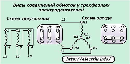
In both cases, the windings are assigned a direction: beginning and end, associated with the installation method - winding during manufacturing.
The windings are numbered in Arabic numerals 1, 2, 3. Their ends are designated K1, K2, K3, and their beginnings are designated H1, H2, H3. For certain types of engines, this marking method may be changed, for example, C1, C2, C3 and C4, C5, C6 or other symbols, or not used at all.

Correctly applied markings simplify the connection of power wires. By creating a symmetrical voltage arrangement on the windings, the creation of rated currents is ensured, ensuring optimal operation of the electric motor. In this case, their shape in the windings fully corresponds to the supplied voltage and repeats it without any distortion.

Naturally, it should be understood that this is a purely theoretical statement, because in practice, currents overcome various resistances and are slightly deflected.
A visual perception of the processes taking place is helped by the image of vector quantities on the complex plane. For a three-phase motor, the winding currents created by the applied symmetrical voltage are depicted as follows.
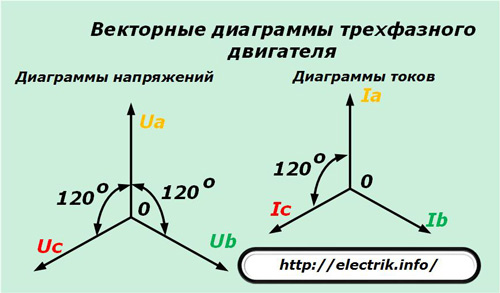
When an electric motor is powered by a voltage system with three vectors evenly spaced in angle and equal in magnitude, the same symmetrical currents flow in the windings.
Each of them forms an electromagnetic field, the induction force of which induces its own magnetic field in the rotor winding. As a result of the complex interaction of the three stator fields with the rotor field, a rotational movement the latter ensures the creation of maximum mechanical power rotating the rotor.
Principles of connecting single-phase voltage to a three-phase motor
For a full connection to three identical stator windings, separated by an angle of 120 degrees, there are no two voltage vectors, only one of them is available.
You can feed it into just one winding and make the rotor rotate. But, it will not be possible to use such an engine effectively. It will have very low shaft power output.
Therefore, the task arises of connecting this phase in such a way that it creates a symmetrical system of currents in different windings. In other words, you need a single-phase to three-phase voltage converter. This problem can be solved using different methods.
If we discard the complex diagrams of modern inverter installations, then the following common methods can be implemented:
1. use of capacitor start;
2. use of chokes, inductive reactors;
3. creation of different directions of currents in the windings;
4. a combined method with equalization of phase resistances to form equal amplitudes for currents.
Let's briefly examine these principles.
Current deviation when passing through a capacitance
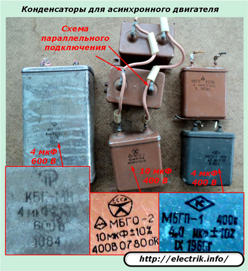
The most widely practiced is capacitor starting, which makes it possible to deflect the current in one of the windings by connecting capacitive reactance, when the current is created to advance by 90 degrees from the applied voltage vector.
Metal-paper structures of the MBGO, MBGP, KBG and similar series are usually used as capacitors. Electrolytes are not suitable for passing alternating current, they explode quickly, and the circuits that involve their use are complex and low in reliability.
In this circuit, the current differs in angle from the nominal value. It deviates only 90 degrees, missing 30 degrees (120-90=30).
Deviation of current passing through an inductance
The situation is similar to the previous one. Only here the current lags behind the voltage by the same 90 degrees, and is thirty degrees short. In addition, the design of the inductor is not as simple as that of a capacitor. It must be calculated, assembled, configured for individual conditions. This method is not widely used.
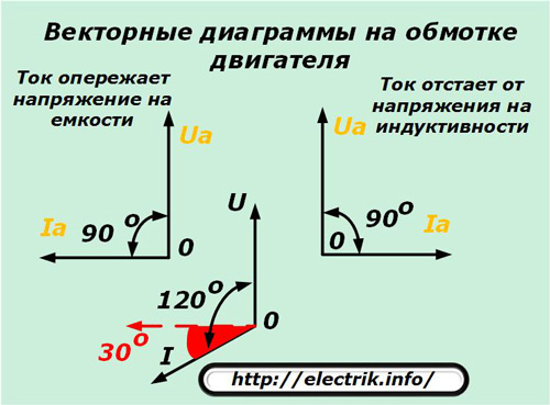
When using capacitors or chokes, the currents in the windings of the electric motor do not reach the required angle per thirty-degree sector, shown in red in the picture, which already creates increased energy losses. But you have to put up with them.
They interfere with creation uniform distribution inductive forces create an inhibitory effect. It is difficult to accurately assess its impact, but a simple approach of dividing the angles results in (30/120 = 1/4) a loss of 25%. However, can it be considered that way?
Current deviation by applying voltage of reverse polarity
In a star circuit, it is customary to connect the phase voltage wire to the input of the winding, and the zero wire to its end.
If you apply the same voltage to two phases separated by 120 o, but separate them, and change the polarity in the second, then the currents will shift in angle relative to each other. They will begin to form electromagnetic fields of different directions, affecting the generated power.
Only with this method the angle of current deviation is obtained by a small value - 30 o.

This method is used in some cases.
Methods for the integrated use of capacitors, inductors, and changing the polarity of windings
The first three listed methods do not allow one to create an optimally symmetrical current deviation in the windings. There is always a skew in their angle relative to the stationary circuit provided for three-phase full power supply. Due to this, counteracting moments are formed, inhibiting spin-up and reducing efficiency.
Therefore, researchers conducted numerous experiments based on different combinations these methods in order to create a converter that provides the greatest efficiency of a three-phase motor. These schemes with detailed analysis electrical processes are given in special educational literature. Their study increases the level of theoretical knowledge, but for the most part they are rarely used in practice.
A good current distribution pattern is created in the circuit when:
1. the direct connection phase is supplied to one winding;
2. voltage is connected to the second and third windings through a capacitor and inductor, respectively;
3. Inside the converter circuit, current amplitudes are equalized by selecting reactances with imbalance compensation by active resistors.
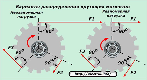
I would like to draw attention to the third point, which many electricians do not attach importance to. Just look at the following picture and conclude that it is possible to rotate the rotor uniformly when forces of equal and different magnitudes are symmetrically applied to it.
The complex method allows you to create a rather complex circuit. It is very rarely used in practice. One of the options for its implementation for an electric motor with a power of 1 kW is shown below.
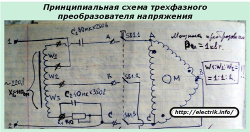
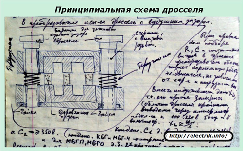
To manufacture the converter, it is necessary to create a complex inductor. This requires time and material resources.
Difficulties will also arise when finding a resistor R1 that will work with currents exceeding 3 amperes. He must:
have a power exceeding 700 watts;
cool well;
reliably isolated from live parts.
There are several more technical difficulties that will have to be overcome to create such a three-phase voltage converter. However, it is quite universal, allows you to connect engines with a power of up to 2.5 kilowatts, and ensures their stable operation.
So, the technical issue of connecting a three-phase asynchronous motor to a single-phase network has been resolved by creating a complex converter circuit. But it has not found practical application for one simple reason, which cannot be eliminated - the excessive power consumption of the converter itself.
Power consumed to create the circuit three-phase voltages with a similar design, exceeds at least one and a half times the needs of the electric motor itself. At the same time, the total loads created on the power supply wiring are comparable to the operation of old welding machines.
The electric meter, to the delight of electricity sellers, very quickly begins to transfer money from the home master’s wallet to the account of the energy supply organization, and the owners do not like this at all. In the end it's complicated technical solution creating a good voltage converter turned out to be unnecessary for practical use in households, and in industrial enterprises too.
4 final conclusions
1. Technically, it is possible to use a single-phase connection of a three-phase motor. For this purpose, many different circuits with different element base have been created.
2. In practice, it is impractical to use this method for long-term operation of drives in industrial machines and mechanisms due to large losses of energy consumption created by extraneous processes leading to low system efficiency and increased material costs.
3. At home, the circuit can be used to perform short-term work on non-critical mechanisms. Such devices can operate for a long time, but the cost of electricity increases significantly, and the power of the operating drive is not provided.
4. For efficient operation of an asynchronous motor, it is better to use a full three-phase power supply. If this is not possible, then it is better to abandon this idea and purchase the appropriate power.
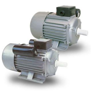
Asynchronous motors
In the “General” section we will consider the scope of application, comparative characteristics, advantages and disadvantages of three-phase and single-phase asynchronous motors. We will also consider the possibility of connecting a three-phase motor to a 220 volt power supply. Asynchronous motors are now widely used in various fields of industry and agriculture. They are used as electric drives in metal-cutting machines, conveyors, lifting and transport machines, fans, pumping equipment etc. Low power motors are used in automation devices. Such a widespread use of electric asynchronous motors is explained by their advantages compared to other types of motors.
Asynchronous motors, depending on the type of supply voltage, are single-phase and three-phase. Single-phase are mainly used up to a power of 2.2 kW. This power limitation is due to too high starting and operating currents. The operating principle of single-phase asynchronous motors is the same as that of three-phase motors. The only difference is that single-phase motors have a lower starting torque.
Operating principle and connection diagrams of three-phase motors
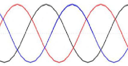
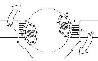
We know that an electric motor consists of two main elements, the stator and the rotor. The stator is the stationary part of the engine, and the rotor is its moving part. Three-phase asynchronous motors have three windings, which are located at an angle of 120° relative to each other. When alternating voltage is applied to the windings, a rotating magnetic field is created in the stator. Alternating current is a current that periodically changes its direction in electrical circuit so that the average value of the current over the period is zero. (Figure 1).
The phases in the figure are shown as sinusoids. The rotating magnetic field of the stator forms a rotating magnetic flux. Since the rotating magnetic field of the stator moves faster than the rotor, it, under the influence of induction currents generated in the rotor windings, creates a magnetic field of the rotor. Magnetic fields stator and rotor form their magnetic fluxes, these flows are attracted to each other and create a torque, under the influence of which the rotor begins to rotate. You can see more details about the operating principle of three-phase motors.
Three-phase motors can have from three to six terminals in the terminal block. These terminals contain either the beginning of the windings (3 terminals) or the beginning and end of the windings (6 terminals). The beginning of the windings is usually designated by the Latin letters U1, V1 and W1, the ends are designated U2, V2 and W2, respectively. In domestic engines, the windings are designated C1, C2, C3 and C4, C5, C6, respectively. In addition, the terminal box may also have additional terminals to which thermal protection built into the windings is output. For motors that have six terminals, there are two options for connecting the windings to a three-phase network: “star” and “delta” (Fig. 2).
A star (Y) connection can be achieved by shorting terminals W2, U2 and V2 together, and applying mains voltage to terminals W1, U1 and V1. With this connection, the phase current equal to current mains, and the phase voltage is equal to the mains voltage divided by the root of three. A star (Y) connection can be obtained by connecting terminals W2, U2 and V2, and applying supply voltage to terminals W1, U1 and V1. With this connection, the phase current is equal to the mains current, and the phase voltage is equal to the mains voltage divided by the root of three. A connection according to the “triangle” (∆) diagram can be obtained by connecting terminals U1 – W2, V1 – U2, W1 – V2 in pairs with jumpers and apply supply voltage to the jumpers. With this connection, the phase current is equal to the mains current divided by the root of three, and the phase voltage is equal to the mains voltage. Using these circuits, you can connect a three-phase asynchronous motor with two voltages. If you look at the nameplate of a three-phase motor, it shows the operating voltages at which this electric motor operates (Fig. 3).
For example, 220-240/380-415: the engine operates at a voltage of 220 volts when its windings are connected in a “triangle” and 380 volts when the windings are connected in a “star”. At lower voltages, the stator windings are always connected in a "delta". For more high voltage the windings are connected in a star. The current consumption when connecting the motor in a “triangle” is 5.9 amperes, when connecting to a “star” the current is 3.4 amperes. To change the direction of rotation of a three-phase asynchronous motor, it is enough to swap any two wires at the terminals.
Operating principle and connection diagram of single-phase motors
Single-phase asynchronous electric motors have two windings that are located at an angle of 90° in relation to each other. One winding is called the main winding, and the second is called the starting or auxiliary winding. Depending on the number of poles, each winding can be divided into several sections. There are differences between single-phase and three-phase motors. A single-phase motor has a change of poles with each cycle, while a three-phase motor has a traveling magnetic field. Single phase electric motor You cannot put it into operation on your own. To launch it use various ways: start through a capacitor and work through a winding, start through a capacitor and work through a capacitor, with a constant starting capacitance, with a rheostat start. The most common are single-phase, eclectic motors equipped with a running capacitor that is permanently connected and connected in series with the starting (auxiliary) winding. Thus, starting winding becomes auxiliary when the electric motor reaches operating speed. How the windings are connected in a single-phase motor can be seen in (Fig. 4)
There are some limitations for single-phase asynchronous motors. Under no circumstances should they operate at low loads or in idle mode, as the engine will overheat. For the same reason, it is not recommended to operate engines at loads less than 25% of full load.
(Fig. 5) shows a nameplate with the characteristics of the motor used in the Pedrollo pump. It contains all the necessary information about the engine and pump. We will not consider the characteristics of the pump.
From the nameplate it is clear that this is a single-phase motor and is designed to be connected to a network with a voltage of 220-230 volts alternating current, a frequency of 50 hertz. Number of revolutions 2900 per minute. The power of this motor is 0.75 kW or one horsepower(NR). Rated current consumption is 4 amperes. The capacitor capacity for this engine is 20 microfarads. The capacitor must have an operating voltage of 450 volts.
Advantages and disadvantages of three-phase motors
The advantages of asynchronous three-phase motors include:
- low price compared to commutator motors;
- high reliability;
- simplicity of design;
- operate directly from AC mains.
The disadvantages of asynchronous motors include:
- the starting current when connected to the network is quite high;
- low power factor, at light loads and at idle;
- To smoothly adjust the rotation speed, it is necessary to use frequency converters;
- consumes reactive power, very often when using asynchronous motors due to lack of power, problems with the supply voltage may arise.
Advantages and disadvantages of single-phase motors
The advantages of single-phase asynchronous motors include:
- low cost;
- simplicity of design;
- long service life;
- high reliability;
- operation from an alternating current network of 220 volts without converters;
- low noise level compared to commutator motors.
The disadvantages of single-phase asynchronous motors include:
- very high starting currents;
- large dimensions and weight;
- limited power range;
- sensitivity to changes in supply voltage;
- at smooth adjustment rotation speed, it is necessary to use frequency converters (frequency converters for single-phase motors are commercially available).
- cannot be used in low load or idle modes.
Despite numerous disadvantages and thanks to many advantages, asynchronous motors operate successfully in various areas industry, agriculture and everyday life. They make life modern man more comfortable and convenient.
Three-phase motor in a single-phase network
Sometimes in life there are situations when some kind of industrial equipment connect to the home network 220 volts. And then the question arises, is it possible to do this? The answer is yes, although in this case losses of power and torque on the engine shaft are inevitable. In addition, this applies to asynchronous motors up to a power of 1-1.5 kW. To run a three-phase motor in a single-phase network, it is necessary to simulate a phase with a shift by a certain angle (optimally 120°). This shift can be achieved by using a phase-shifting element. The most suitable element is a capacitor. (Fig. 6) shows diagrams for connecting a three-phase motor to a single-phase network when connecting the windings in star and delta.
When starting an engine, an effort is required to overcome the forces of inertia and static friction. To increase the torque, you need to install an additional capacitor, connected to the main circuit only at the time of startup, and after startup it must be turned off. For these purposes the best option the SA locking button will be used without fixing the position. The button should be pressed at the moment the supply voltage is applied, and the starting capacitance Sp. will create an additional phase shift. When the engine spins up to rated speed, the button must be released, and only the working capacitor Srab will be used in the circuit.
Calculation of capacity size
The capacitance of the capacitor can be determined by selection, starting with a small capacitance and gradually moving to larger capacitances until a suitable option is obtained. And when it is still possible to measure the current (its lowest value) in the network and on the working capacitor, then you can select the most optimal capacitance. Current measurements must be carried out with the engine running. The starting capacity is calculated based on the requirement to create sufficient starting torque. But this process is quite lengthy and labor-intensive. In practice, a faster method is often used. There is a simple way to calculate capacity, although this formula gives rather the order of the numbers, but not its value. And in this case you will also have to tinker.
Serb =66 Pn
Where
Рн – rated engine power kW.
This formula is valid when connecting the windings of a three-phase motor in a delta. Based on the formula, for every 100 W of three-phase motor power, a capacitance of about 7 μF will be required.
If the capacitor capacitance is selected larger than necessary, the engine will overheat, and if the capacitance is smaller, the engine power will be underestimated.
In some cases, in addition to the working capacity Srab. A starting capacitor Sp is also used. The capacity of both capacitors must be known, otherwise the engine will not work. First, we determine the value of the capacitance required to make the rotor rotate. When connected in parallel, the capacity Srab and Sp. fold up. We also need the value of the rated current In. This information we can look at the nameplate attached to the engine.
The capacitor capacity is calculated depending on the connection diagram of the three-phase motor. When connecting the motor windings to a star, the capacitance is calculated using the following formula:
Serb =2800 I/U;
In the case of connecting the motor winding in a “triangle”, the working capacitance is calculated as follows:
Serb =4800 I/U;
Where:
Srab – working capacitance of the capacitor in μF;
I – rated current in amperes;
U – voltage in volts.
The capacity of the additional starting capacitor should be 2 - 3 times greater than the capacity of the working capacitor. If, for example, the capacitance of the working capacitor is 70 µF, then the starting capacitance of the capacitor should be 70-140 µF. Which in total will be 140-210 uF.
For three-phase motors with power up to 1 (kW), only the operating capacitor Srab is sufficient; the additional capacitor Sp does not need to be connected. When selecting a capacitor for a three-phase motor connected to a single-phase network, it is important to correctly take into account its operating voltage. The operating voltage of the capacitor must be at least 300 Volts. If the capacitor has a higher operating voltage, in principle nothing bad will happen, but at the same time its dimensions and, of course, the price increase. If a capacitor is selected with an operating voltage less than required, the capacitor will very quickly fail and may even explode. Very often there are situations when there is no capacitor of the required capacity. Then it is necessary to connect several capacitors in parallel or in series to obtain the required capacitance. It must be remembered that when parallel connection several capacitors, the total capacitance is added up, and when connected in series, the total capacitance is reduced based on the formula: 1/C=1/C1+1/C2+1/C3... and so on. You should also not forget about the operating voltage of the capacitor. The voltage on all connected capacitors in parallel must be not lower than the rated voltage. And the voltage on the connected capacitors in series, on each of the capacitors may be less than the rated one, but the total sum of the voltages should not be lower than the rated one. Let me give you an example: there are two capacitors with a capacity of 60 uF with an operating voltage of 150 volts each. When connecting them in series, their total capacity will be 30 μF (decreased), and the operating voltage will increase to 300 volts. That's probably all.
Thank you for your interest.
Connection
Any asynchronous three-phase motor is designed for two rated voltages of a three-phase network 380/220 - 220/127, etc. The most common are 380/220V motors. Switching the motor from one voltage to another is done by connecting the windings “star” - for 380 V or “delta” - for 220 V. If the engine has a connection block that has 6 terminals with jumpers installed, you should pay attention to the order in which the jumpers are installed . If the engine does not have a block and there are 6 leads, they are usually collected in bundles of 3 leads. The beginnings of the windings are collected in one bundle, and the ends in the other (the beginnings of the windings are indicated by a dot in the diagram).
In this case, “beginning” and “end” are conditional concepts, it is only important that the directions of the windings coincide, i.e., in the example of a “star”, the zero point can be both the beginning and the ends of the windings, and in a “triangle” the windings must be connected in series, i.e. the end of one to the beginning of the next. To correctly connect to a “triangle”, you need to determine the terminals of each winding, arrange them in pairs and connect them in sequence. diagram:

If you expand this diagram, you will see that the coils are connected in a “triangle”.
If the motor has only 3 terminals, you should disassemble the motor: remove the cover from the block side and find the connection of three winding wires in the windings (all other wires are connected in 2). The connection of the three wires is the zero point of the star. These 3 wires should be broken, the lead wires soldered to them and combined into one bundle. Thus, we already have 6 wires that need to be connected in a triangle pattern.
Method for determining the beginnings and ends of the windings of a three-phase asynchronous motor
First you need to define the windings. To do this, the windings are tested with an ohmmeter and collected into conventional bundles of 3 pieces. 
A battery is connected to the terminals of one of the windings (for example A1-A2), and a dial voltmeter is connected to the terminals of the other winding (B1, B2) (a digital multimeter will not work - it is too inert). (see diagram below)
At the moment the contact of winding A with the battery breaks, the voltmeter needle will swing to a certain point. side.
We leave the battery on the same winding (maintaining the polarity), and connect the voltmeter to the next winding - C. By changing the polarity of winding C (switching the winding leads), we achieve a deflection of the voltmeter in the same direction as in the previous case. 
Thus (see diagram 1), when the contact of winding A with the battery is broken, the voltmeter, being connected to winding B and connected to winding C, should swing the arrow in one direction. If the arrow deviates in different directions, swap (arranged in different bundles) pins B1 and B2 or C1 and C2.
Connect the battery to the terminals of winding C (see diagram) and in the same way ensure that when the contact with the battery is broken, the arrow of the voltmeter connected to winding A jerks in the same direction as if the voltmeter is connected to winding B. If the arrow swings in different directions on winding A and winding B, - swap the leads of winding A. (maintain the polarity of the voltmeter and battery)
Check everything again from the very beginning.
This should result in the following.
when the battery contact with any of the windings is broken, a short-term electric potential of the same polarity should appear on the other two windings (i.e., the voltmeter needle should swing in one direction).
Now the pins located in one bundle need to be marked as “beginnings”, and the pins located in the other bundle – as “ends”