The linear current when connecting the phases of the receiver with a triangle is equal to the difference in the vectors of those two phase currents that are associated with it by Kirchhoff’s first law.
Shape of phase e curve. d.s. in the presence of a third harmonic in magnetic flux rod.| Determination of the shape of the curve of the reactive component of the magnetizing current in the presence of a third harmonic in the magnetic flux of the rod.| The emergence of current coupling FS, caused by currents r3 of triple frequency, creating electromagnetic interference IN COMMUNICATION LINES. The linear current, equal to the difference in phase currents, has a characteristic saddle-shaped shape (Fig. 2 - 59, i); third harmonics, present in phase currents, are absent in linear currents.
The line current is equal to the difference between the phase currents, therefore, there will be no third harmonics in the line current: they form a zero-sequence system, therefore the difference between the third harmonics of the phase currents is zero.
Line currents can be determined using a phasor diagram, as shown in Fig. 5.6. At asymmetrical load phase and line current systems are asymmetrical. However, changing the load in the phases of the receiver does not violate the symmetry of the voltages in the same way as when connecting a star to a neutral wire.
The line current is set within 40 t-b O for a single-wire system and 20 - 1 - 25 mA for four.
Linear current is observed in the field of two parallel, near a flat boundary, linear wires with currents / and 4 directed in opposite directions. Comparing Fig. 3 - 17 and 3 - 18, we are convinced that in the region / (above the xOy plane) the conditions for both problems are the same. If you select the fictitious current It in such a way that the boundary conditions of the main problem are satisfied, you can easily calculate the field vector in the region /.
Linear current / flows along the Z axis from the infinitely distant point z - oo to the origin. In the XY plane it1 spreads from the origin in all directions uniformly.
Linear current / flows along the Z axis in the positive direction, originating at the infinitely distant point z - oo.
We determine linear currents graphically using a vector diagram.
We will determine the linear currents graphically using a vector diagram, for which we will find the active and reactive currents of the phases.
Linear currents with a uniform load, equal to the differences of the corresponding phase currents, also form a symmetrical system of currents (Fig.
The linear current when the phases of the receiver are connected by a triangle is equal to the difference in the vectors of those two phase currents that are associated with it by Kirchhoff’s first law.
The line current is equal to the geometric difference of the two phase currents. The linear current vector connects the ends of the phase current vectors drawn from one point and is directed towards the one being reduced.
Linear current/A is determined from the phasor diagram.
Linear currents are determined graphically from the vector diagram presented in the figure.
For problem 8 - 10.| For problem 8 - 10.| For problem 8 - 10. Linear current is equal to the geometric difference of two phase currents.
Linear current 1A is determined from the vector diagram.
Linear currents 1B and 1c are equal in magnitude to phase currents IAB and ICA, respectively, as follows from Fig. 51, and Eqs. If it is necessary to determine the phase angles of currents relative to voltages, then this can be done using a protractor by measuring the angles between the corresponding nectors on a diagram drawn on a sufficiently large scale.
Linear current is observed in a two-parallel field - near the flat boundary of linear wires with currents / and / x directed in opposite directions. The environment in which these wires are located is homogeneous with the permeability of the cg. Comparing Fig. 3 - 17 and 3 - 18, we are convinced that in the region / (above the xOy plane) the conditions for both problems are the same.
Inbox line currents with two-pole telegraphy they must exceed the inductive interference currents by 15 mA.
A linear current of force / flows along an infinite contour formed by the sides of a right angle.
Linear currents IAg, Ibc and AC form a closed triangle.
The linear currents of the electricity consumer are determined based on the vector diagram in Fig. 7.8: 1l - 15 9 A; / - 15 9 A; / s 27 32 A.
Three-phase circuit with a midpoint. Current curves when connecting transformer windings D / Y. Linear currents of the primary winding are obtained, as usual for a three-phase system, by calculating the differences of the corresponding phase currents.
Surface and linear currents associated with singularities /(r) are usually not considered in calculations. This corresponds to neglecting motion along the z axis in a real star.
The relatively small linear currents used in membrane electrolysers make the use of this type of contact technically possible.
The first harmonic linear currents 1A, 1B and 1C are determined according to Kirchhoff's first law.
The EMSF linear current curves are distorted to a much lesser extent than the converter current curves; The distortions of the voltage curves caused by the operation of the EMSF also turn out to be smaller.
The first harmonic linear currents I A, 1B and 1C are determined in accordance with Kirchhoff’s first law.
Star connection.| Delta connection. Linear current / l is the current flowing in one of the wires of a three-wire (three-phase) line.
Determine line currents and voltages if the load is connected by a star and the phase voltages are 220 V.
Determine linear currents and power and construct a vector diagram of voltages and currents.
Determine the linear currents and the current in the neutral wire, if the resistance of the neutral wire can be neglected, and the resistance of the receivers: Zl 6 j8 ohm; Z2 - / 20 ohm; Z3 10 ohm.
Find the linear currents if the resistances of the groups of lamps are equal: ZAB10 ohm; ZBC 2Q ohm; ZCA22 ohm.
Determine the line currents and voltages of each phase if the load is connected by a star and the phase voltages are the same and equal to 127 V.
Determine the linear current in the network (current in the primary winding of the autotransformer), if it is known that the transformation ratio is 1 73, and the linear current of the motor when directly connected to the network is 60 A.
Determine the total line current consumed by the motors.
The calculated linear current in amperes is determined by the two largest values of phase currents.
To the conditions of the problem §.| Vector diagram of the circuit shown in. Determine the phase and line currents, as well as the active power of the entire circuit, if the line voltages are 380 V.
Determine the phase and line currents if a receiver whose phases are connected by a triangle is connected to a network with symmetrical line voltages Un 220 V.
Determine the phase and line currents if a phase receiver connected by a triangle is connected to a network with symmetrical line voltages and 127 V.
Maximum permissible values of no-load current for 1st three-phase asynchronous motors. The arithmetic mean value of the measurement results in three phases is taken as the linear no-load current.
Determine phase and line currents; construct a vector diagram to scale, indicating the voltage and current vectors on it.
The actual consumed linear current / is taken to be the arithmetic mean of the three measured values.
Determine phase and line currents; power consumed by the receiver; 2) construct a vector diagram of voltages and currents.
The arithmetic mean of the three measured values is taken as the actual linear no-load current / o.
Three-phase circuits: phase and linear currents, voltages, powers
Three-phase electrical circuit called a connected set of three electrical circuits in which sinusoidal EMFs of the same frequency operate, shifted relative to each other in phase and created by a common energy source - a three-phase generator. The individual chains that make up such a chain are called phases and are usually designated by letters A, IN, WITH, and the set of emfs acting in these phases, as well as the set of phase currents and voltages, is called three-phase system of EMF, currents and voltages. A three-phase system of EMF (currents, voltages) is called symmetrical, if the EMF (currents, voltages) of all phases are equal in amplitude and are shifted relative to each other in phase by an angle of 2π/3, otherwise a three-phase system is called asymmetrical. Balanced called such a three-phase circuit, the instantaneous power of the elements of which does not depend on time, and unbalanced- otherwise. Balance is important quality three-phase circuit. Thus, the torque on the shaft of a three-phase generator remains constant in such systems, and does not pulsate with an angular frequency of 2ω, as would be the case in a single-phase generator, the instantaneous power of which varies with a frequency of 2ω. Let's show this using the example of a circuit with a symmetrical EMF system:
Then the instantaneous power of the three-phase generator p = p A + p B + p C = 3EI cosφ = R= const does not depend on time.
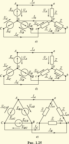
In three-phase systems, two main methods of connecting elements are used - delta connection And star connection. In Fig. 1.25, A presents a complex equivalent circuit circuit, generator phase ( A, IN, WITH) and receiver ( A, b, With) which are connected by a star to the neutral wire connecting nodes 0 and 0 " ; in Fig. 1.25, b- star connection diagram without neutral wire; in Fig. 1.25, V presents a complex equivalent circuit of a circuit whose generator and receiver phases are connected by a triangle. In the case of symmetry of both the generator and the load, the current I 0 in neutral wire, connecting nodes 0 and 0 " in the circuit fig. 1.25, A, is equal to zero: I 0 = I A + I B + I C= 0. It is often absent in such connections (Fig. 1.25, b), and then only three are used to connect generators and receivers linear wires with currents I A, I B, I C instead of the six wires that would be required if three unrelated single-phase circuits were used. This is another advantage of three-phase systems. When the currents in the phases are unbalanced, current flows through the neutral wire I 0, the amplitude of which is usually less than the amplitude of linear currents I A, I B, I C. Therefore, the cross-section of the neutral wire is chosen to be smaller than the cross-section of the linear wires.
When connecting a symmetrical generator with a triangle (see Fig. 1.25, V) the sum of the phase EMF is zero, therefore, in the absence of linear currents I A, I B, I C(mode "idle") there are also no currents in the generator phases. Note that in the diagram in Fig. 1.25, V Only three wires are used to connect the generator and the load.
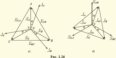
In Fig. 1.26, A presents a vector diagram of currents and voltages of the circuit shown in Fig. 1.25, A, in the case of symmetry of both the EMF system and the load, and in Fig. 1.26, b A similar diagram is presented for a symmetrical circuit in Fig. 1.25, V. The load is considered active-inductive (i.e.  ). From consideration of the stress triangle (Fig. 1.26, A) it follows that linear voltages U AB = UBC = U CA = U l are associated with phase voltages U A = U B = U C = U f ratio
 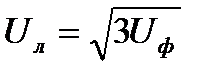 . Similarly, considering the triangle of currents (Fig. 1.26, b), we can write a relation for the connection of linear I A = I B = I C = I l and phase I AB = I BC = I CA = I f currents:
 ![]() . Taking into account that when connecting the receiver branches with a star U f = U l/, I f = I l, and when connecting them with a triangle U f = U l, U f = I l / , we have for the active power of the receiver regardless of the connection R= Z U f I f cosφ = , U l I l cosφ.
. Taking into account that when connecting the receiver branches with a star U f = U l/, I f = I l, and when connecting them with a triangle U f = U l, U f = I l / , we have for the active power of the receiver regardless of the connection R= Z U f I f cosφ = , U l I l cosφ.
Similarly for the apparent and reactive powers of a symmetrical three-phase receiver
The symmetrical three-phase system of EMF (voltages, currents) discussed above is called symmetrical direct sequence system. In it, the phase angles of the EMF (voltages, currents) are reduced by 2l;/3 in the order of the phases A, B, C- as this is shown for EMF in Fig. 1.28, A. Along with such a system, electrical engineering uses symmetrical negative sequence system, in which the phase angles of the EMF (voltages, currents) decrease by 2l/3 in the order of phases A, WITH, IN(see Fig. 1.28, b) And symmetrical system EMF (voltage, current) zero sequence, in which the phase angles of the EMF (voltages, currents) coincide. It is obvious that the analysis of symmetric systems of negative and zero sequences can also be reduced to the problem of analyzing one phase, for example the phase A.
To solve the problem of analyzing a three-phase circuit of a general form, i.e. such a circuit in which the systems of phase EMF (voltages, currents) are not
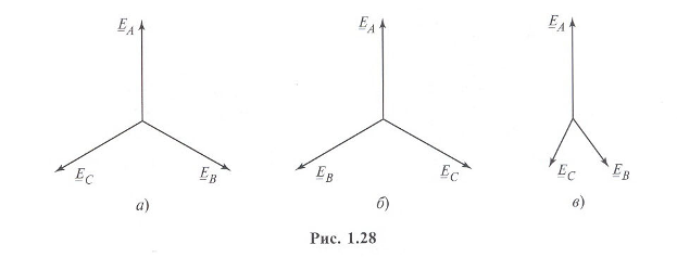
symmetrical systems, i.e. the amplitudes of these EMFs (voltages, currents) are not equal in value and/or the shift angles of the EMFs (voltages, currents) are not equally equal to 0, ![]() (Fig. 1.28, V), then such a three-phase circuit can be considered simply as a complex circuit. In electrical engineering, however, the calculation of even such circuits is reduced to the calculation of only one of their phases - usually the phase A. This is possible when using method of symmetrical components (Fortescue method). According to this method, any asymmetrical three-phase EMF (voltage, current) system is represented as the sum of three symmetrical three-phase EMF (voltage, current) systems, respectively, direct, negative and zero sequences, the calculation of which is very simple and can be carried out for one phase. Thus, the concept of symmetrical three-phase systems of EMF (voltages, currents) in electrical engineering is used to describe processes even in such circuits in which there are actually no such systems of such EMFs (voltages, currents).
(Fig. 1.28, V), then such a three-phase circuit can be considered simply as a complex circuit. In electrical engineering, however, the calculation of even such circuits is reduced to the calculation of only one of their phases - usually the phase A. This is possible when using method of symmetrical components (Fortescue method). According to this method, any asymmetrical three-phase EMF (voltage, current) system is represented as the sum of three symmetrical three-phase EMF (voltage, current) systems, respectively, direct, negative and zero sequences, the calculation of which is very simple and can be carried out for one phase. Thus, the concept of symmetrical three-phase systems of EMF (voltages, currents) in electrical engineering is used to describe processes even in such circuits in which there are actually no such systems of such EMFs (voltages, currents).
Linear voltages differ from phase voltages by √3 times.
U AB =U A -U B, V
U BC =U B -U C, V
U CA =U C -U A , V
Currents in the neutral wire:
I N =I A +I B +I C, A
P=√3Uicosφ, W
Q=√3Uisinφ, var
Triangle– this is a connection when the end of the first winding of the source is connected to the beginning of the second, the end of the second to the beginning of the third, the end of the third to the beginning of the first; line wires are connected to the connection points of the windings.
When connecting in a triangle:
Linear and phase voltages are equal
Linear currents differ from phase currents by √3 times.
I A =I AB -I CA, A
I B =I BC -I AB, A
I C =I CA -I BC, A
Powers are determined by the formula
P=√3Uicosφ, W
Q=√3Uisinφ, var
The task of calculating a three-phase circuit is to determine the currents in the phases of the receiver, in the wires of the line, as well as the power of the receiver in each phase and in general, if the line voltages are specified, the phase resistances. In a symmetrical circuit, the phase resistances of the receiver are the same, and a symmetrical system of linear voltages operates at its terminals. For such a circuit, it is enough to calculate one phase, since the currents and powers in all phases are the same in magnitude.
Example 4
. To the generator (Figure 34) with line voltage U l =220 B is connected to a consumer connected by a triangle. Active resistance of each phase of the consumer R f =8 Ohm, inductive X Lf = 6 Ohm.
Determine the current in each phase of the generator, the power it produces and construct a vector diagram.
Figure 34
Solution. Voltage on each consumer phase U f equals line voltage generator U l, since the consumer is connected by a triangle.
U f = U l = 220 V
Phase resistance:
Z ph = √ R ph 2 + X Lph 2 = √ 8 2 + 6 2 = 10 Ohm.
I f = U f / Z f = 220 /10 = 22 A.
Linear current of a delta-connected consumer:
I l =√3Iph=1.73∙22=38 A.
Power supplied by the generator (active power):
Р =√3 U l ∙ I l ∙сosφ = 1.73 ∙ 220 ∙ 38 ∙ 0.8 =11570 W,
сosφ = R f / Z f = 8/10 = 0.8; then φ = 37 o
i.e., the consumer phase current lags behind the voltage by an angle φ = 37°, the load is inductive. The calculated values formed the basis for constructing a vector diagram (Figure 35).
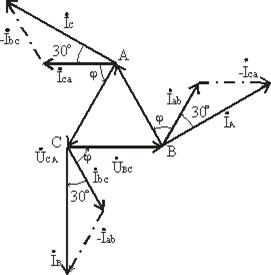 Figure 35
Questions for test work №2.
Option 1
1. Petroleum and electrical insulating oils. Technology for their production
2. Glass: composition, methods of production, properties. Quartz. Quartz glass. Application of glass in electrical engineering.
Option 2
1. Soapite: composition and properties. Capacitor ceramics.
2. Natural and synthetic rubbers. Their shortcomings. Vulcanization technology.
Option 3
1. Classification of electroceramics. Electrical porcelain, its components, manufacturing technology, basic electrical and mechanical characteristics porcelain.
2. Fluoroplastic-4. physico-chemical, thermal and mechanical properties.
Option 4
1. Mica-based insulating materials: micanites, micafolia, mycalentes, micanites.
2. Electrical insulating papers and cardboards. Production technology, varieties, technological requirements, application.
Option 5
1.Use of various gaseous dielectrics.
2.Polystyrene. Polyethylene. Polyurethane. Polyvinyl chloride. Electrical, mechanical, thermal characteristics and applications.
Option 6
1.Properties and scope of plastics. Laminated plastics.
2. Synthetic liquid dielectrics. Varieties, properties, applications.
Option 7
1. Mineral dielectrics: asbestos and asbestos cement, their properties and application.
2. Compounds: classification, purpose, components, application in electrical engineering.
Option 8
4. Enamels composition, properties, classification, brands, application of enamels.
5.Polyvinyl chloride. Polyvinyl chloride plastic compound. Source materials and production technology. Electrical, mechanical, thermal characteristics and application of polymers.
Option 9
1. Organosilicon, polyamide dielectrics. Their preparation, properties and application.
2. Fiber, its production and use. Textile electrical insulating materials.
Option 10
1. Plastics: production technology, composition and classification.
2. The concept of varnishes, requirements for them. Composition and classification of varnishes, their scope.
Introduction 4
1 Three-phase electrical circuit 5
1.1 Determination of phase and line currents 6
1.2. Determining the voltage between points a and b 8
1.3 Determination of active power of a three-phase circuit 9
1.4 Construction of a vector diagram of currents and topographic
voltage diagrams 10
Conclusion 15
List of sources used 16
Introduction
All circuit calculation methods AC are divided into two groups: calculation based on instantaneous values and calculation based on effective values of currents and voltages.
When calculating using instantaneous values, equations are compiled according to Kirchhoff's laws for instantaneous values. This results in a system of differential equations. We calculate the instantaneous values of currents and voltages for individual moments of time lagging behind each other by the time interval t.
When calculating using effective values, the shape of voltages and currents is reduced to sinusoidal. Express a sinusoidal quantity in complex form and compose a system of equations in complex form. An algebraic system of equations with complex coefficients is obtained, which can be solved in general form through determinants.
The most commonly used calculation is based on the effective values of currents and voltages using the complex amplitude method (symbolic method).
Currently, there are a number of computer programs that can be used to easily perform calculations in the time domain. For example, Micro-Cap.
1 Three-phase electrical circuit
Figure 1 shows a diagram of a three-phase circuit. It contains a three-phase generator (creating a three-phase symmetrical sinusoidal EMF system) and a symmetrical load. The effective value of the generator phase EMF E A , period T, parameters R 1 , L, C 1 are given in Table 1. The initial phase of the EMF e A is taken to be zero.
Required:
1.1 Determine phase and linear currents;
1.2 Determine the voltage between points a and b;
1.3 Determine the active power of a three-phase circuit;
1.4 Construct a vector diagram of currents and a topographic diagram of voltage;
Table 1 - Initial data for the problem
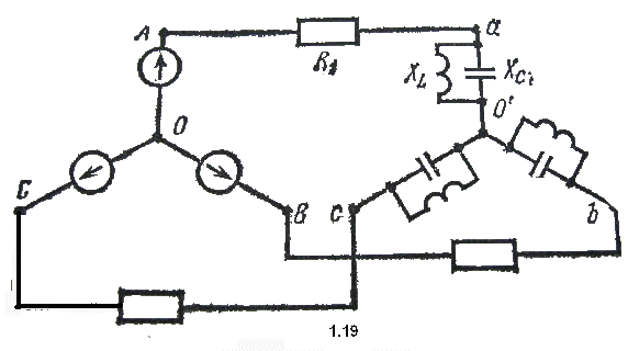
Figure 1 - Scheme 1.19
Determination of phase and line currents
To find any voltage, you need to know the currents. When connected by a star, the line currents are equal to the phase currents. The load is symmetrical, so the neutral wire does not need to be turned on, since its current will still be zero. The magnitudes of the phase currents will be equal, and the phase shift between them will be 120 degrees. In this regard, it is possible to calculate only one phase, for example phase A.
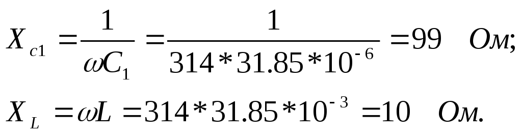
We use a symbolic calculation method, in which resistances, currents and voltages must be presented in a complex form. Let's first calculate the resistance of the reactive elements. Power supply frequency f = 1/T = 1/0.02 = 50 Hz. Angular frequency ω = 2πf = 314 s -1.

Line wire resistance (see Figure 2)
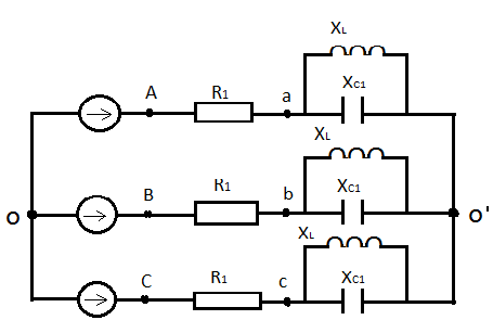
Figure 2 – Three-phase linear diagram
Let's find the impedance complex of phase A
The complex of the effective value of the first phase current is equal to
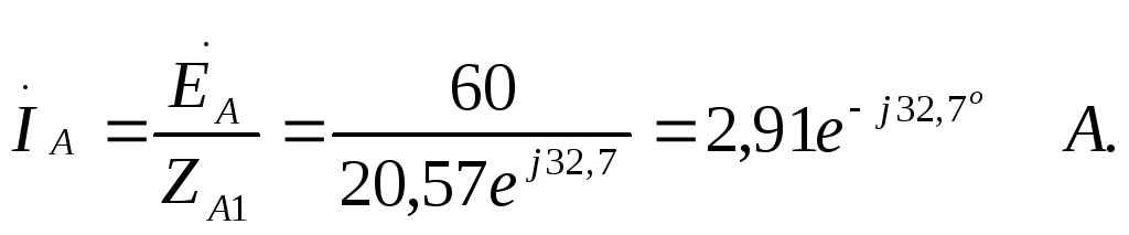
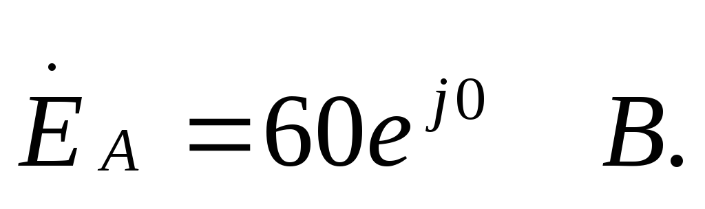
Here the complex of the effective value of the emf of phase A is equal to
The EMF and currents of the other two phases differ from each other only in the phase angles of 120 o.
1.2 Determination of voltage between pointsaAndb
To find the voltage U ab, you need to draw a circuit that includes this voltage and apply Kirchhoff’s second law (see Figure 3).
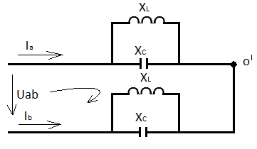
Figure 3 - Chain section
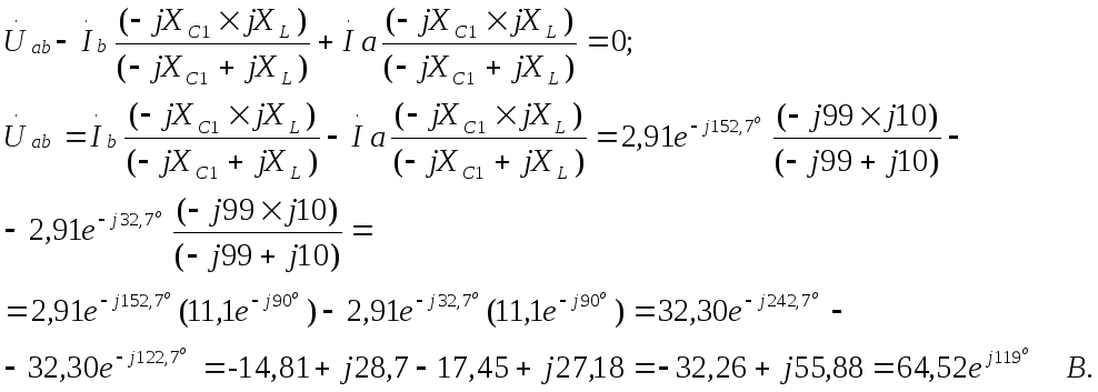
The instantaneous voltage value is
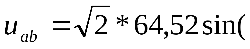 314t+119 0) B.
1.3 Determination of active power of a three-phase circuit
Let's define the active power in phase A as
P A = I 2 A *R 1 =  2 *17.32 =146.66 W.
The active power of the entire three-phase circuit is equal to
P = 3*P A = 3*146.66 = 439.98 W.
1.4 Construction of a vector diagram of currents and a topographic diagram of voltages
We select the scales of currents and voltages. The number of volts and amperes per unit length must be a multiple of 1, 2, 5 multiplied by 10 ± n, where n is any integer. The choice of scale depends on the values of currents and voltages that need to be depicted on the diagram. We write down the complexes of current and voltage of phase A:
On the topographic diagram (Figure 4) it is required to show the potentials of all points indicated in the diagram in Figure 1.
Figure 4 - Current diagram and topographic voltage diagram
Conclusion
In this course work, a three-phase electrical circuit is presented, shown in Figure 1. Using this diagram, I determined the phase and linear currents, the voltage between points a and b, the active power of the three-phase circuit, and constructed a vector diagram of currents and a topographic diagram of voltage.
List of sources used
Bessonov L.A. Theoretical foundations of electrical engineering. Electrical circuits. graduate School. M: - 1984-559 p.
Nekrasova N.R., Panfilov S.A. Computer technology laboratory, computational and graphical and coursework in electrical engineering. Moscow State University. Saransk: -2004-102 p.