Very often, buyers of power supplies ask about the possibility of parallel or serial connection of units. This feature is present in all models of BVP Electronics power supplies. We recommend that you use several rules when connecting two or more power sources. When connecting sources in parallel, it is necessary that all sources have the same output voltage rating (for example, 15V/100A and 15V/10A, the output will be 15V/110A). When connecting sources in series, it is necessary that all sources have the same output current rating (for example, 30V/30A and 15V/30A, the output will be 45V/30A). Connecting sources with different ratings can lead to failure of the units.
1. Parallel connection of power supplies (increasing output current)- Place power sources at the workplace, if possible close to each other, ensuring ease of work with the sources and conditions for natural ventilation.
- Connect the output cords between the negative terminals of the sources and the positive terminals separately (see Fig. 1). In this case, we recommend using the proposed table when choosing the cross-section of the output cord (Table 1). To obtain guaranteed output parameters of sources at a remote load, connecting output wires of such a cross-section are required that the maximum load current creates a voltage drop of no more than 0.5 - 1.0 V.
Table 1.
- Turn on the power supplies without load (by moving the "ON/OFF" toggle switches to the "ON" position).
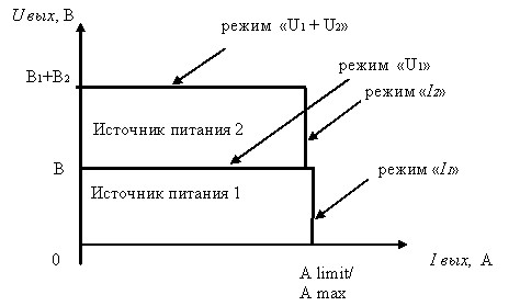
If you smoothly change the load resistance from infinity to zero, then the operating point (Fig. 2), first from the voltage axis (no-load point) of the first power source (usually higher in output voltage) will move to the right along the horizontal line of the “U1” mode, and then, when the current reaches the value "A limit 1", the first source will switch from voltage stabilization mode to current stabilization mode (the red LED will light up) and the second power source will be connected. Next, the operating point will move along the voltage axis "U2", and when the current reaches the value "A limit 2", the second source will switch from voltage stabilization mode to current stabilization mode, "I2" mode (the red LED on the second source will light up).
Further along the vertical line “I2”, the operating point will drop down to the current axis. The point of contact of the current axis corresponds to short circuit. When the load resistance changes in the opposite direction, the mode switching will occur, accordingly, in the reverse order.
The value of the real output current "A out" will be equal to the sum of the values "A limit 1" and "A limit 2" and will not depend on changes in the load. Only the output voltage will depend on changes in load.
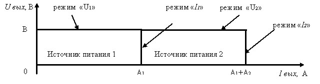
Rice. 2. Current-voltage characteristics in parallel
connecting two power supplies
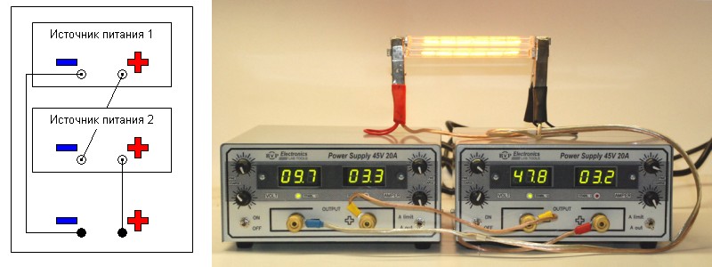
Example of parallel connection of two BVP Electronics power supplies (45V/20A and 45V/20A)
The required output load power is 1345 Watts (42V*32A).
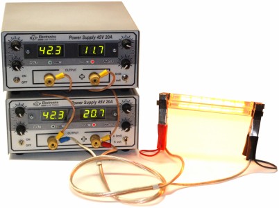
Rice. 3
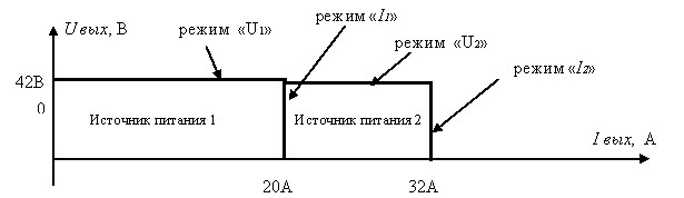
Rice. 4. Current-voltage characteristics with parallel connection
two power supplies BVP 45V 20A
2. Serial connection of power supplies (increasing output voltage)
Serial connection of power supplies manufactured by BVP Electronics is possible, but with preliminary preparation. BVP Electronics power supplies are generally grounded to the negative terminal. Therefore, before connecting the blocks in series, it is necessary to disconnect the grounding of the sources. At the same time, it is imperative to ground the equipment that they will power.
To disconnect the grounding of the sources, it is necessary to remove the top cover of the device (unscrew four screws (in metal blocks - located on the sides of the case, in plastic - on the legs of the source - Fig. 5).
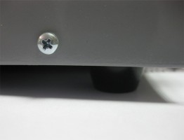
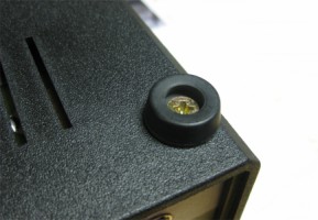
Rice. 5. Location of screws on metal and plastic housings
power supplies manufactured by BVP Electronics
On the left side there is a ground connector. To disconnect the source grounding, you need to move the jumpers to the middle terminals. Figure 6 shows grounding options: using the negative terminal, positive terminal and without grounding.
Rice. 6. Jumper Location for Grounding/Disconnection
power supply grounding
Close the device housing cover and tighten the screws. The power supplies are not grounded.
Many people ask, is it possible to connect power supplies without disconnecting the ground? It is possible if you connect the sources to a power outlet or extension cord without ground. But at the same time, you must understand that when the sources are connected in series, the body of the blocks will be energized. Therefore, power supplies should not be placed so close to each other that they touch metal parts or housings. For safety reasons, you need to work with such power sources very carefully.
To connect power supplies in series, you must
use the following instructions:
- Place power sources at the workplace, if possible close to each other, ensuring ease of work with the sources and conditions for natural ventilation.
- Set the "ON/OFF" switches located on the front panel of the sources to the "OFF" position.
- Connect the power cords to the connectors on the rear panel of the cases and the power supply.
- Connect the output cord between the positive terminal of the first power source and the negative terminal of the second source, and connect the negative terminal of the first source and the positive terminal of the second with output cords (see Fig. 7). In this case, we recommend using the proposed table when choosing the cross-section of the output cord (Table 1). To obtain guaranteed output parameters of sources at a remote load, connecting output wires of such a cross-section are required that the maximum load current creates a voltage drop of no more than 0.5 -1.0 V.
Rice. 7. Series connection of power supplies
(output voltage 58V, output current 3A)
- Turn on the supply voltage using the "POWER" switches located on the rear panels of the sources.
- Turn on the power source without load (by moving the "ON/OFF" toggle switch to the "ON" position).
- Set the "Fine/Coarse" voltage regulators to the required output voltage, which is the same on all sources.
- Use the "A limit/A out" switch to select the "A limit" position. Set the current regulators "Fine/Coarse" to the maximum or required value.
- Use the "A limit/A out" switch to select the "A out" position.
- Turn off the source (by moving the "ON/OFF" toggle switch to the "OFF" position).
- Observing polarity, connect the load.
- Turn on the power source (by moving the "ON/OFF" toggle switch to the "ON" position).
- The operation of the sources with a load will be indicated by green LEDs on the front panel of the sources, and indications of the current flowing in the load circuit on the digital ammeter indicators.
If you smoothly change the load resistance from infinity to zero, then the operating point (Fig. 8), first from the total voltage axis (no-load point) of the first and second power sources, will move to the right along the horizontal line of the “U1 + U2” mode, and then when reaching output current value "A limit 2" (based on the lower value of the set current) will switch from the voltage stabilization mode to the current stabilization mode "I2" (the red LED will light up).
Rice. 8
Further along the vertical line “I2”, the operating point will drop down to the current axis. In this case, when the horizontal axis of voltage “U1” is reached, the flowing current will switch to the value “A limit 1”. The point of contact of the current axis corresponds to a short circuit. When the load resistance changes in the opposite direction, the mode switching will occur, accordingly, in the reverse order.
For safety reasons, you should work with series or parallel connected power supplies very carefully. When operating sources without grounding, there is a high probability of sources failure.
If you have any questions about working with switching power supplies, the BVP Electronics team will help you! Call, write, we are always glad to see you!
Sincerely,
BVP Electronics team,
Kiev, Ukraine
www.site
Comments to the article: 14
| #3 | Witch | | 26.01.2011 10:24 | | |
| Good day. Do I understand correctly that when two power sources are connected in parallel to increase the maximum current value, the red indicator will light on one of them or both? Another question - we use power supplies to charge batteries. The specificity of the charging algorithm is such that the current first increases for about a minute, and then charging continues in the minimum current - maximum current mode. That is, the power supply throws between virtually no load and a maximum of 30 amperes. Is this normal for a single block and will it be normal for a parallel bundle? |
|||
| #4 | Svetlana, BVP Electronics | | 27.01.2011 12:57 | | |
| It is correct if the power supplies operate in current stabilization mode. When the load increases from zero to maximum, first one block will fail for the maximum current (in the article in Fig. 2 there is a vertical line “Power source 1”), and then a second one, if the maximum load is greater than the total currents of the power supplies. As we understand, your batteries are charged not directly from power supplies, but through an additional device that works according to a special algorithm. For our power supplies, working both separately and in combination, it makes no difference whether they work at idle or under load. |
|||
| #9 | Oleg | | 20.02.2011 10:06 | | |
| One pulse block power supply is good, but two - twice as much interference. Popular amateur radio wisdom. In the parameters and descriptions of your sources, nowhere is there any talk about electromagnetic compatibility, namely the level of radiation in the electromagnetic spectrum (medium wave range, short wave and probably already relevant VHF (FM)). In particular, in the short wave range it is impossible to listen to radio stations and work on the air due to various pulse converters, power supplies and chargers. Please provide a couple or more measurements of radiation from your sources, at least on HF!!! I will be glad if you refute the “folk amateur radio wisdom”. Thanks in advance. Oleg. |
|||
| #10 | Svetlana, BVP Electronics | | 22.02.2011 12:49 | | |
| Thanks for interesting question. In order to answer this, we turned to the passports and instructions of televisions, monitors, computers, microwave ovens, etc., that is, to the equipment used in quality switching power supply. Such a parameter as electromagnetic compatibility there isn't. Contacted the certification center where we were told that measuring such a parameter is very difficult: The equipment for measuring it is too expensive, and not in all centers she is. Next, we had difficulty finding a receiver that worked on long, medium and short waves. Unfortunately, find a wave with radio broadcasting we were unable to due to the presence of too many city noise. We were only able to draw one conclusion - ultra short Our power supplies are not a hindrance to waves (VHF, FM). Possible benefits use of switching power supplies in technology (creation of laptops, microwave ovens, energy saving light bulbs, plasma and LCD TVs) mean much more than the loss quality of radio broadcasting on long, medium, short radio waves. AND a parameter such as electromagnetic compatibility is not studied. Perhaps the “ham radio wisdom” you cited will be stored on the shelf where Popov’s electric-arc receiver is stored, or will receive a new interpretation, like: “they used to measure the road in fathoms and arshins, but now they use cars.” Good luck to you in amateur radio and new discoveries! |
|||
In cases where the rated voltage or rated current and power of the source electrical energy turn out to be insufficient to power the receivers; instead of one, two or more sources are used. There are two main ways to connect sources: serial and parallel.
The series connection (Fig. 1.18) is usually carried out in such a way that the emf of the sources is directed in one direction. Characteristic for a series connection is the same current I of all sources, for which each of them must be designed.
According to Kirchhoff's second law
By connecting sources in series, you can get more high voltage U at the output pins a and b, which is why this connection method is used.
Electric circuit fig. 1.18 can be replaced by a circuit with an equivalent generator having parameters Ee and r0e (Fig. 1.19). According to the equivalent generator method, the EMF Ee at no-load (r = ∞, I = 0) should be equal to the open-circuit voltage, Ee = Ux. Taking this into account, based on Kirchhoff’s second law for the circuit in Fig. 1.18 we get
When connecting sources in parallel (Fig. 1.20), the positive terminals of all sources, as well as their negative terminals, are connected to each other. Characteristic for a parallel connection is the same voltage U at the terminals of all sources. For the electrical circuit in Fig. 1.20, the following equations can be written:
As can be seen, when the sources are connected in parallel, the current and power of the external circuit are equal, respectively, to the sum of the currents and powers of the sources. Parallel connection of sources is used primarily when the rated current and power of one source are insufficient to power the receivers. Sources with the same EMF, power and internal resistance are usually switched on for parallel operation. Using the nodal voltage method, it is easy to show that in this case, when the external circuit is disconnected, the source currents will be equal to zero, and when the external circuit is connected, they will be the same.
11. Intrinsic electronic and hole electrical conductivity
Semiconductors are substances that, in terms of their electrical conductivity, occupy an intermediate position between conductors and dielectrics.
For semiconductors
characterized by a negative temperature coefficient of electrical resistance. As temperature increases, the resistance of semiconductors decreases, rather than increases, as with most solid conductors. In addition, the electrical resistance of semiconductors greatly depends on the amount of impurities, as well as on external influences such as light, electric field, ionizing radiation, etc.
There are two types of electrical conductivity in semiconductors. Like metals, semiconductors have electronic conductivity, which is caused by the movement of conduction electrons. At normal operating temperatures, semiconductors always contain conduction electrons, which are very weakly bound to the nuclei of atoms and undergo random thermal movement between the atoms of the crystal lattice. These electrons, under the influence of a potential difference, can receive additional movement in a certain direction, which is an electric current.
Semiconductors also have hole electrical conductivity, which is not observed in metals. In semiconductors, the crystal lattice is quite strong. Its ions, i.e. atoms deprived of one electron, do not move, but remain in their places.
The absence of an electron in an atom is conventionally called hole.
This emphasizes that the atom is missing one electron, i.e., a free space has formed. Holes behave like elementary positive charges.
With hole conductivity, electrons actually also move, but more limitedly than with electron conductivity. Electrons move from these atoms only to neighboring ones. The result of this is the movement of positive charges - holes - in the direction opposite to the movement of electrons.
Electrons and holes that can move and therefore create electrical conductivity are called mobile charge carriers
or just charge carriers.
It is commonly said that under the influence of heat, pairs of charge carriers are generated, i.e., pairs arise: conduction electron – conduction hole.
Due to the fact that electrons and conduction holes undergo chaotic thermal motion, the opposite process to the generation of carrier pairs also necessarily occurs. Conduction electrons again occupy free places in the valence band, i.e., they combine with holes. This disappearance of carrier pairs is called recombination of charge carriers.
The processes of generation and recombination of pairs of carriers always occur simultaneously.
A semiconductor without impurities is called an intrinsic semiconductor. It has its own electrical conductivity, which consists of electron and hole electrical conductivity. Moreover, despite the fact that the number of electrons and conduction holes in the intrinsic semiconductor is the same, electronic conductivity predominates, which is explained by the greater mobility of electrons compared to the mobility of holes.
Chemical sources of electrical energy (galvanic cells, batteries) for collaboration can be connected in series, parallel or mixed. A group of sources connected to each other in one way or another forms a battery. Only homogeneous sources that have the same emf are combined into batteries. and internal resistances.
Serial connection sources of electrical energy are used in cases where the consumer voltage exceeds the emf of one source, and the rated current of the consumer does not exceed the normal discharge current of one source.
To connect the sources into a battery in series, you need to connect the negative pole of the first source (Fig. 14) to the positive pole of the second, the negative pole of the second to the positive pole of the third, etc. The external circuit is connected to the positive pole of the latter, i.e. to the remaining free poles of the battery. In this case, the emf. sources are directed in one direction.
E.m.f. of the entire battery when the sources are connected in series is equal to their sum:
E = E 1 + E 2 +…+ E k. (48)
Taking into account the fact that only homogeneous sources are connected to batteries, we have
where n is the number of sources connected to the battery;
E k – emf. one of the sources included in the battery.
The internal resistance of the battery is equal to the sum of the internal resistances of the individual sources:
r = r 1 + r 2 +…+r k , (50)
r = n·r k, (51)
where r k – internal resistance one of the sources included in the battery.
Battery capacity when connecting homogeneous sources in series equal to the capacity of one source . It should be noted that battery capacity It is customary to call the amount of electricity, expressed in ampere-hours (Ah), that a fully charged battery can supply to the circuit when discharged with a rated current to the set final voltage.
When connecting electrical energy sources in series with identical internal resistances, the current strength in the circuit is determined by the formula
 , (52)
The number of battery sources required to obtain a given voltage U in the external part of the circuit
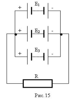
Parallel connection sources of electrical energy are used in cases where the consumer current is greater than the rated discharge current of one source, and the consumer voltage is equal to the emf. one source. To connect sources of electrical energy into a battery in parallel, you need to combine their positive poles into one node, and the negative poles into another.
When connected in parallel, the emf. battery is equal to e.m.f. one source:
Battery internal resistance
decreases as many times as the number of sources with resistance r k included in it.
The battery capacity is equal to the sum of the capacities of parallel connected sources.
In the case of parallel connection of electrical energy sources with the same emf. and internal resistances, the current strength in the circuit is determined by the formula:
where R is the resistance of the external circuit.
The number of battery sources n required to produce a given current in the external circuit.
I Р – discharge current of one source.
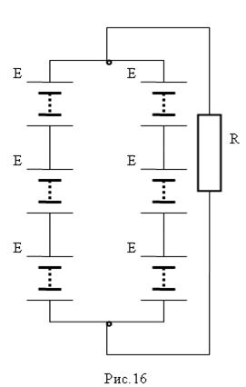
A mixed connection of electrical energy sources is used in the case when the voltage and current of the consumer is greater than the voltage and discharge current of one source.
The current in the circuit is determined by dividing the sources into equal groups in which they are connected in series, and then into branches where they are connected to each other in parallel:
where n Г is the number of sources connected into one group;
m – number parallel branches.
The number of series-connected sources n Г in the group and the number of parallel branches m are found using the previously given formulas.
Example. Two parallel groups of batteries, each with three batteries connected in series, operate on an external circuit with a resistance of 3.55 Ohms. E.m.f. 2 V batteries, internal resistance 0.003 Ohm. Determine the battery voltage, current and power supplied by the battery to the external circuit.
Solution. E.m.f. groups
E G = n G E K = 3 2 = 6 B.
E.m.f. the entire battery will be equal to the emf. E G of one series-connected group, that is, E b = E G = 6 V.
Current strength in the external circuit

Voltage in the external circuit U = IR = 1.6·3.55≈5.7 V.
The power supplied to the external circuit is
P = UI = 5.7 1.6 = 9.12 W.
Security questions and tasks
1.What is electric charge and what is its unit of measurement?
2. How and in accordance with what laws they apply electric charges among themselves?
3.What is the electric field strength called and how to determine its value at a point in space?
4.What is meant by electric field potential and in what units is it measured?
5.What is called electric voltage and emf. and what unit is it measured by?
6.What is current strength and what is its unit of measurement? What is current density called?
7.What is meant by electrical resistance? What unit is used to measure it?
8. How can the resistance of a conductor be determined if its material, length and cross-section are known?
9.Tell about electrical conductivity and its unit of measurement.
10.Formulate Ohm’s law for a section of a circuit and a complete circuit.
11.What is the relationship between electromotive force and voltage of the energy source?
12. On what factors does the voltage at the generator terminals depend when its emf remains unchanged?
13.Explain the essence of idle mode and short and source circuit.
14.Write the work formula electric current. In what units is the work of electric current measured?
15.What is called electrical power and what is its unit of measurement?
16.Formulate the Joule-Lenz law and write its formula.
17.Explain how the cross-section of wires is selected according to heating conditions.
18.Explain the procedure for calculating wire cross-sections for a given voltage loss.
19.Tell us about series, parallel and mixed connections of resistances and chemical energy sources.
20.Formulate Kirchhoff’s first and second laws, outline calculation methods electrical circuits with their use.