STEAM BOILER AUTOMATION
course work for the course “Management of technical systems”
Moscow State Civil Engineering University (MGSU)
Department of Electrical Engineering and Electric Drive
Performed by a student of the MiAS 4-1 group
Lukantsov D.S.,
Checked
Associate Professor of the Department of Electrical Engineering and Electric Drive, Ph.D.
Becker Yu.L.
BRIEF DESCRIPTION OF THE BOILER ROOM
The boiler room of the Teplogorsk Foundry and Mechanical Plant is designed to generate steam released for cooking hot water and heating of workshops. The heating system is closed. The fuel for the boiler room is gas with a calorific value of Qn = 8485 kcal/m 3 .
The boiler room is equipped with two DKVR - 20/13 boilers without superheaters. Boiler productivity in accordance with the calculated data is 28 t/hour. Steam pressure 13 kgf/cm2. The maximum amount of heat produced by the boiler room in the form of hot water is 100%. Condensate return 10%. The source water for feeding the boilers is clarified river water or artesian water. The boiler unit DKVR - 20/13 Fig. 3 is equipped with a single-pass cast iron economizer of the VTN system with pipes 3 m long. The power regulator is installed upstream of the VEC, and cannot be switched off for both gas and water.
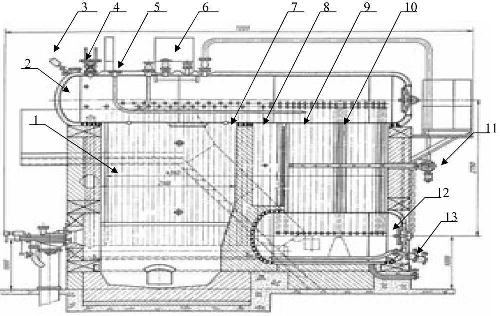
Fig.1. Boiler brand DKVR
1- screen pipes; 2- upper drum; 3- pressure gauge; 4- safety valves; 5- feed water pipes; 6- steam separator; 7- safety plug; 8- afterburning chamber; 9- partitions; 10- convective tubes;
11-blowing device; 12- lower drum;
13- purge pipeline.
A discharge line with an automatic device is provided to limit the increase in water temperature after WEC above 174°C. The movement of gases in the economizer from top to bottom. Gases from the economizer are directed to a smoke exhauster installed in the walls of the boiler room. The blower fan is mounted under the boiler. The fan takes in air through a metal duct. The supply air to the burner devices passes through the boiler foundation. The boiler is equipped with three gas and oil burners GMGP Fig. 2.
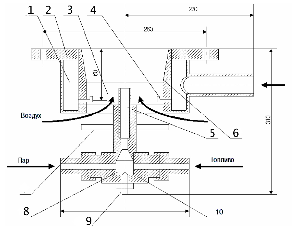
Rice. 1. Gas-oil burner GMGP-120
1-gas part; 2-flange; 3-air part; 4-gas nozzle; 5-barrel; 6-diffuser; 7-petal; 8-fluid nozzle; 9-adjusting screw; 10-case
Nominal thermal power burners GMGP-120 - 1.75 MW. It is designed for co-combustion of gas and fuel oil. The atomization of fuel oil is provided by water vapor. The burner is equipped with a diffuser (6), which sets the torch opening angle, and has separate gas (4) and fuel oil (5) nozzles. Air is supplied to the internozzle space. Due to the recessed position of the nozzles, an ejection effect is created at the burner outlet. The design of the burner ensures easy ignition of the furnace when starting up the installation (gas supply only), good mixing of atomized liquid fuel with air, and suction of flue gases into the root of the torch (ejection effect). The supply of air into the internozzle space (between the gas and liquid fuel flows) creates conditions for two-stage fuel combustion.
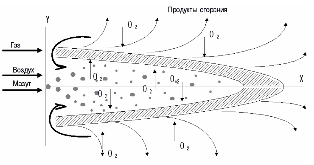
Fig.2. Burner flame profile GMGP-120
Figure 2 shows the flame profile of the GMGP-120 injector with dual-frontal fuel combustion. Primary air is supplied to the internozzle space with an excess air coefficient of ~1.0 and mixed with liquid fuel. The evaporated fuel and air oxygen enter the internal combustion front, where incomplete combustion occurs. Chemical underburning products burn almost completely in the outer flame front. Oxygen enters the outer front of the latter by diffusion from the air sucked through the nozzle embrasure into the combustion space. The total excess air coefficient a is 1.10–1.15. In addition, due to the ejection effect, flue gases are sucked into the root of the torch, reducing the oxygen content in the air supplied to the internozzle space, which leads to a decrease in the combustion temperature by 50–70°C.
Lowering the combustion temperature slows down the rate of chemical reactions and leads to a noticeable lengthening of the flame. Considering that in a technological furnace about 80% of the heat is transferred by radiation, the radiation heat flux remains practically unchanged and the thermal balance of the furnace is maintained.
DKVR boilers consist of the following main parts: two drums (upper and lower); screen pipes; screen collectors (chambers).
Boiler drums for a pressure of 13 kgf/cm 2 have the same internal diameter (1000 mm) with a wall thickness of 13 mm.
For inspection of drums and devices located in them, as well as for cleaning pipes with cutters, there are manholes on the rear bottoms; The DKVR-20 boiler with a long drum also has a hole on the front bottom of the upper drum.
To monitor the water level, two water indicator glasses and a level indicator are installed in the upper drum. For boilers with a long drum, water indicator glasses are attached to the cylindrical part of the drum, and for boilers with a short drum, to the front bottom. From the front bottom of the upper drum, impulse tubes are routed to the power regulator. In the water space of the upper drum there is a feed pipe; for DKVR 20-13 boilers with a long drum there is a pipe for continuous blowing; in the steam volume - separation devices. The lower drum contains a perforated pipe for periodic purging, a device for heating the drum during kindling, and a fitting for draining water.
The side screen collectors are located under the protruding part of the upper drum, near the side walls of the lining. To create a circulation circuit in the screens, the front end of each screen collector is connected by a lower unheated pipe to the upper drum, and the rear end by a bypass pipe to the lower drum.
Water enters the side screens simultaneously from the upper drum through the front drop pipes, and from the lower drum through the bypass pipes. This power supply circuit for the side screens increases the reliability of operation when reduced level water in the upper drum, increases the circulation rate.
Screen pipes of DKVR steam boilers are made of steel 51×2.5 mm.
In boilers with a long upper drum, the screen pipes are welded to the screen collectors and rolled into the upper drum.
The pitch of the side screens for all DKVR boilers is 80 mm, the pitch of the rear and front screens is 80–130 mm.
Boiler tube bundles are made of seamless bent steel pipes with a diameter of 51×2.5 mm.
The ends of the boiling pipes of steam boilers of the DKVR type are attached to the lower and upper drums using rolling.
Circulation in the boiling pipes occurs due to the rapid evaporation of water in the front rows of pipes, because they are located closer to the firebox and are washed by hotter gases than the rear ones, as a result of which in the rear pipes located at the outlet of gases from the boiler the water is flowing not up, but down.
The combustion chamber, in order to prevent the flame from being drawn into the convective beam and to reduce entrainment losses (Q 4 - from mechanical incomplete combustion of fuel), is divided by a partition into two parts: the firebox and the combustion chamber. The boiler partitions are designed in such a way that the flue gases wash the pipes with a cross current, which promotes heat transfer in the convective beam.
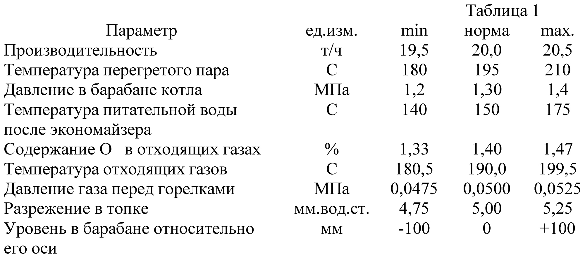
Technological parameters
2. AUTOMATION OF STEAM BOILER OPERATION
Justification of the need for monitoring, regulation and signaling of technological parameters.
Regulating the power supply of boiler units and regulating the pressure in the boiler drum mainly comes down to maintaining a material balance between steam removal and water supply. The parameter characterizing the balance is the water level in the boiler drum. The reliability of the boiler unit is largely determined by the quality of level control. When the pressure increases, a decrease in the level below permissible limits can lead to disruption of circulation in the screen pipes, resulting in an increase in the temperature of the walls of the heated pipes and their burning.
An increase in the level also leads to emergency consequences, since water may enter the superheater, which will cause it to fail. In this regard, very high demands are placed on the accuracy of maintaining a given level. The quality of power regulation is also determined by the equality of feedwater supply. It is necessary to ensure uniform water supply to the boiler, since frequent and profound changes in feedwater flow can cause significant temperature stresses in the economizer metal.
Boiler drums with natural circulation have a significant storage capacity, which manifests itself in transient conditions. If in stationary mode the position of the water level in the boiler drum is determined by the state of the material balance, then in transient modes the position of the level is influenced by large number disturbances. The main ones are changes in feedwater consumption, changes in boiler steam output when the consumer load changes, changes in steam production when the furnace load changes, and changes in feedwater temperature.
Regulating the gas-air ratio is necessary both physically and economically. It is known that one of the most important processes occurring in a boiler plant is the process of fuel combustion. The chemical side of fuel combustion is the oxidation reaction of combustible elements with oxygen molecules. Oxygen in the atmosphere is used for combustion. Air is supplied to the furnace in a certain ratio with gas by means of a blower fan. The gas-to-air ratio is approximately 1.10. If there is a lack of air in the combustion chamber, incomplete combustion of the fuel occurs. Unburned gas will be released into the atmosphere, which is economically and environmentally unacceptable. If there is excess air in the combustion chamber, the firebox will cool, although the gas will burn completely, but in this case, the remaining air will form nitrogen dioxide, which is environmentally unacceptable, since this compound is harmful to humans and the environment.
The automatic control system for the vacuum in the boiler furnace is designed to maintain the furnace under pressurization, that is, to maintain a constant vacuum (approximately 4 mm water column). In the absence of vacuum, the torch flame will be pressed, which will lead to burning of the burners and the lower part of the firebox. In this case, flue gases will go into the workshop premises, which makes it impossible for maintenance personnel to work.
Salts are dissolved in the feed water, the permissible amount of which is determined by the standards. During the steam generation process, these salts remain in the boiler water and gradually accumulate. Some salts form sludge - solid, crystallizing in boiler water. The heavier part of the sludge accumulates in the lower parts of the drum and collectors.
An increase in the concentration of salts in boiler water above the permissible values can lead to their entrainment into the superheater. Therefore, salts accumulated in the boiler water are removed by continuous blowing, which in this case is not automatically regulated. The calculated value of blowing steam generators under steady-state conditions is determined from the equations for the balance of impurities in water in the steam generator. Thus, the proportion of blowdown depends on the ratio of the concentration of impurities in the blowdown and feed water. How better quality feed water and the higher the permissible concentration of impurities in the water, the lower the proportion of blowdown. And the concentration of impurities, in turn, depends on the proportion of additional water, which includes, in particular, the proportion of lost blowdown water.
Alarm parameters and protections that act to stop the boiler are physically necessary, since the operator or boiler driver is not able to keep track of all the parameters of a functioning boiler. As a result, there may be emergency. For example, when water is released from the drum, the water level in it decreases, as a result of which circulation may be disrupted and the pipes of the bottom screens may burn out.
The protection, which is activated without delay, will prevent failure of the steam generator. When the steam generator load decreases, the combustion intensity in the furnace decreases. Combustion becomes unstable and may stop. In this regard, protection is provided for extinguishing the torch.
The reliability of protection is largely determined by the number, switching circuit and reliability of the devices used in it. According to their action, protections are divided into active ones, stopping the steam generator; reduction of steam generator load; performing local operations.
According to the above, automation of the operation of a steam boiler should be carried out according to the following parameters: maintaining constant steam pressure;
to maintain a constant water level in the boiler;
to maintain the gas-air ratio;
to maintain vacuum in the combustion chamber.
3. SELECTION OF AUTOMATIC CONTROL SYSTEM.
3.1. To automate the operation of the boiler, select
programmable controller of the MIKROKONT-R3 family
MIKROKONT-R3 programmable controllers have a modular design, which allows you to arbitrarily increase the number of inputs and outputs at each control and information collection point. High computing power of the processor and developed network tools make it possible to create hierarchical automated process control systems of any complexity.
3.2. Design of the microcontroller MICROCONT
This microcontroller has a modular design (Fig. 4). All elements (modules) of the family are made in closed housings of a single design and are oriented for installation in cabinets. The connection of input/output modules (EXP) to the computer module (CPU) is carried out using a flexible expansion bus (flat cable) without the use of a chassis that limits expansion options and reduces layout flexibility.
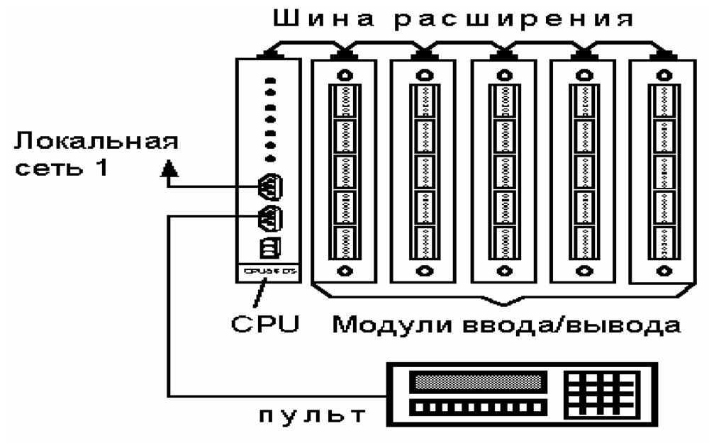
Fig.4
This microcontroller includes the following modules:
Processor module
MP-320 central processor DS80C320, RAM-96 K, EPROM-32 K, FLASH-128 K.
I/O modules
Bi/o16 DC24 discrete input/output, 16/16 =24 V, Iin=10 mA, Iout=0.2 A;
Bi 32 DC24 discrete input, 32 signals = 24 V, 10 mA;
Bi16 AC220 discrete input, 16 signals ~220 V, 10 mA;
Bo32 DC24 discrete output, 32 signals = 24 V, 0.2 A;
Bo16 ADC discrete output, 16 signals ~220 V, 2.5 A;
MPX64 discrete input switch, 64 inputs, DC 24 V, 10 mA;
Ai-TC 16 analog thermocouple inputs;
Ai-NOR/RTD-1 20 analog inputs i or U;
Ai-NOR/RTD-2 16 i or U inputs, 2 resistance thermal converters;
Ai-NOR/RTD-3 12 i or U inputs, 4 resistance thermal converters;
Ai-NOR/RTD-4 8 i or U inputs, 6 resistance thermal converters;
Ai-NOR/RTD-5 4 i or U inputs, 8 resistance thermal converters;
Ai-NOR/RTD-6 10 resistance thermal converters; PO-16 remote control (display - 16 letters, 24 keys).
I/O modules have I/O connectors with screw terminals that combine the functions of connectors and terminal connections, which simplify equipment space in the cabinet and provide quick connection/disconnection of external circuits.
Operator console
RO-04 - remote control for installation on a switchboard. LCD - indicator (2 lines of 20 characters each), built-in keyboard (18 keys), ability to connect 6 external keys, RS232/485 interface, power supply = unstabilized 8–15 V;
RO-01 - portable remote control. LCD - indicator (2 lines of 16 characters), keyboard, RS232/485 interface, power supply: a) = 8–15 V; b) battery.
For preparing and debugging automation application programs technological equipment envisaged the use personal computer(IBM PC type), connected to the information network channel via an AD232/485 adapter.
Application programs are prepared in one of two languages:
* RKS (technological programming language that operates with standard elements of relay logic and auto control;
*ASSEMBLER.
It is possible to compose a program from modules written in any of the specified languages. When debugging application programs of a module, the normal mode of operation of application programs of other modules and exchange over the channel is maintained local network.
3.3. Purpose and technical specifications main microcontroller modules
MP-320 processor module
The module is designed to organize intelligent systems control and performs the functions of the central processor of a programmable controller.
Objects are controlled through input/output modules connected to the MP module via an expansion bus. Communication with the upper level and with other controllers is carried out through serial ports (up to 4) RS485 or RS232.
The MP-320 module can be connected to two local BITNET networks (slave-master; mono-channel; twisted pair; RS485; 255 subscribers) and perform the functions of both master and slave in both networks.
The MP-320 module can perform the functions of an active repeater between two local network segments (up to 32 subscribers in each segment).
The MP-320 module includes a power supply used both to power internal elements and to power input/output modules (up to 10 input/output modules).
Main technical characteristics
Connecting I/O Modules (EXP)

Connection of input/output modules to the MP-320 module is carried out using a flexible expansion bus (flat cable, 34 cores).
I/O modules can be located either to the left or to the right of the processor.
The maximum extension bus cable length is 2500 mm.
The maximum number of connected I/O modules is 16. When connecting more than 10 I/O modules to the bus, it is recommended to place them equally on different sides of the CPU
Analog input module
The Ai-NOR/RTD analog input module is designed for automatically scanning and converting signals from sensors with normalized current output and from resistance thermal converters into digital data and then recording them into dual-port memory, accessible to the CPU module via an expansion bus.
Full designation of the analog input module Ai-NOR/RTD-XXX-X:
the first two letters indicate the module type: Ai - analog input. The following letters indicate the type of input signal: NOR - normalized analog signal, RTD - resistance thermal converter).
The next three digits determine:
the first digit is the number and ratio of analog inputs. There are six options for the ratio of normalized inputs and inputs from resistance thermal converters.
Ai-NOR/RTD-1X0 -20 normalized inputs, no RDT inputs;
Ai-NOR/RTD-2XX - 16 standardized inputs, 2 RTD inputs;
Ai-NOR/RTD-3XX - 12 standardized inputs, 4 RTD inputs;
Ai-NOR/RTD-4XX — 8 standardized inputs, 6 RTD inputs; Ai-NOR/RTD-5XX — 4 standardized inputs, 8 RTD inputs;
Ai-NOR/RTD-60X - no standardized inputs, 10 RTD inputs.
the second digit is the range of the normalized current or potential input signal. There are seven options for normalized signals.
Ai-NOR/RTD-X1X - input signal range -10 V10 V;
Ai-NOR/RTD-X2X - input signal range 0 V10 V;
Ai-NOR/RTD-X3X - input signal range -1 V1 V;
Ai-NOR/RTD-X4X - input signal range -100 mV-100 mV;
Ai-NOR/RTD-X5X - input signal range 0-5 mA;
Ai-NOR/RTD-X6X - input signal range 0-20 mA;
Ai-NOR/RTD-X7X - input signal range 4-20 mA.
the third digit is the type of resistance thermal converter. Connection of five types of resistance thermal converters is provided.
Ai-NOR/RTD-XX1 - resistance thermal converter - copper type TSM-50M, value W100=1.428;
Ai-NOR/RTD-XX2 - resistance thermal converter - copper type TSM-100M, value W100=1.428;
Ai-NOR/RTD-XX3 - resistance thermal converter - platinum type TSP-46P, value W100=1.391;
Ai-NOR/RTD-XX4 - resistance thermal converter - platinum type TSP-50P, value W100=1.391;
Ai-NOR/RTD-XX5 - resistance thermal converter - platinum type TSP-100P, value W100=1.391.
The temperature range and electrical resistance of thermal converters are given in Table 2.
The closing letter of the code is the type of terminal connection (cable connection): R - connection on the right, L - connection on the left, F - connection from the front.
Table 2 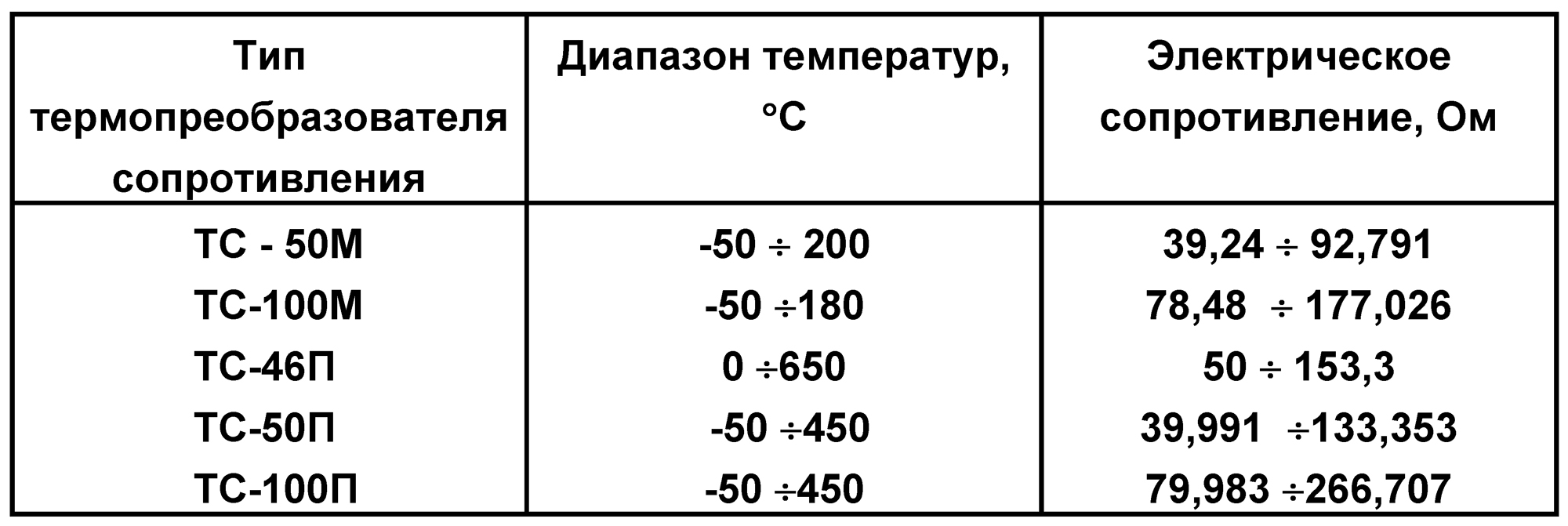
Connection to CPU module
The connection to the CPU module is made using a flexible expansion bus.
The maximum length of the expansion bus depends on the type of CPU module used and is indicated in its technical description. The distribution of distribution bus signals across contacts and their purpose is given in the technical description for the CPU module. The maximum number of analog input modules connected to one CPU is determined by their consumption from the power supply built into the CPU, but should not exceed 8.
To address the analog module in the address space of the CPU module, there is an address switch on the rear panel of the analog module. Each analog module connected to the CPU module expansion bus must be set to an individual address using a switch. The allowed address setting range is from 0 to 7 (according to the switch position).
Description of the module operation
The Ai-NOR/RTD analog signal input module converts standardized current signals and thermal resistance signals into digital data.
Conversion of input analog signals is carried out by automatic sequential scanning (connection) of input circuits to the input of a common normalizing amplifier. The input signal (0–10) V, amplified by a normalizing amplifier, is fed to a highly stable analog-to-frequency converter, the conversion time of which is 20 ms or 40 ms and is set by software.
The analog-to-frequency converter linearly converts the input voltage (0–10) V to a frequency (0–250) kHz. The number of pulses generated by the converter for a set time is recorded in the pulse counter, which is part of the single-chip computer of the analog module. Thus, the digital value recorded in the counter is the raw digital value of the analog input signal.
The single-chip computer of the module processes the received digital values:
– linearization,
– temperature drift compensation,
– offsets (if necessary),
– checking analog sensors for breaks.
The necessary data to implement the above functions is stored in the electrically rewritable ROM of the module.
The processed digital values of analog signals are placed in dual-port memory, accessible to the CPU module via an expansion bus.
Exchange on the expansion bus with the CPU module is provided through dual-port RAM using the “command-response” principle. The CPU module writes the analog data transfer command code and the analog input channel number to the dual-port RAM of the analog module. The single-chip computer of the analog module reads the received command from the dual-port RAM, and, provided that the requested signal is fully processed, places the response code into the dual-port RAM. When a response code is received, the CPU module writes the processed digital value of the requested analog channel into its buffer and proceeds to request and enter the next channel.
After entering the last analog channel, the CPU module queries the analog module “status” register, which displays the status internal devices module, as well as the serviceability of analog sensors, and only after that proceeds to entering the first analog channel. The “status” register is stored in the memory of the CPU Unit. In addition, the CPU memory stores the contents of the EEPROM of the analog module, which is overwritten once when the power is turned on, as well as a “control” register, which includes input of analog data. All data related to the analog module is readable software top level, for example, the “Directory” program.
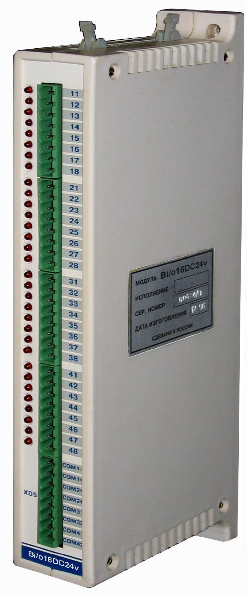
Discrete input/output module
The discrete input/output module is designed to convert discrete input signals DC from external devices to digital data. Transmitting them via the expansion bus to the processor module (CPU), as well as for converting digital data coming from the processor module into binary signals, amplifying them and outputting them to output connectors for controlling devices connected to them.
All inputs and outputs are galvanically isolated from external devices.
Main technical characteristics
Number of inputs - 16 Number of outputs - 16
Type of galvanic isolation:
- by entrance - group; one common wire for every four inputs
- and outputs - one common wire for every eight inputs
Input parameters:
power supply of input circuits - external source (24–36) V,
— logical one level — >15V
— logical zero level —<9В
Output parameters:
— rated input current — 10 mA
— power supply of output circuits — external source (5–40) V
— maximum output current — 0.2A
Module supply voltage - +5V
Current consumption - 150 mA
MTBF - 100,000 hours.
Operating temperature range - from -30°С to +60°С
Relative ambient humidity - no more than 95% at 35°C
Degree of protection from environmental influences - IP-44
Operator console
The OR-04 operator console (hereinafter referred to as the console) is designed to implement a human-machine interface (MMI) in monitoring and control systems based on MIKROCONT-R2 controllers or others that have a freely programmable RS232 or RS485 interface.
Specifications
Communication interface - RS232 or RS485;
Communication speed - programmable from the range: 300, 600, 1200, 2400, 4800, 9600, 28800,57600;
Number of LCD indicator lines - 2;
The number of characters per line is 20;
The height of the character in the line is 9.66 mm;
Numeric keyboard - 18 keys;
Degree of protection - IP56;
Supply voltage - +10–30 V (unstabilized); or 5 V (stabilized);
Power consumption - no more than 2.0 W;
MTBF - 100,000 hours;
Ambient temperature - from -10° to +60°С;
Average service life - 10 years;

The remote control consists of:
CPU from ATMEL.
32 kBytes of RAM.
interface chips of type ADM241 (DD2) or ADM485 for matching the TTL level of the processor with the RS232 or RS485 interface, respectively.
power supply based on the LT1173-5 chip.
register with SPI interface for keyboard scanning and LCD control. The CPU controls exchanges with external devices, scans the keyboard and displays information on the liquid crystal display. The liquid crystal display has two lines of 20 characters. The connected keyboard has 24 keys: 6 scan lines * 4 data lines. When you press any key, an INT0 interrupt is generated on the CPU. OR – 04 allows you to control LCD based on the HD44780 controller from HITACHI. The OR-04 uses a 4-bit communication interface with an LCD module. OR-04 interfaces with an external device via RS232 or RS485 interface. In the first case, a microcircuit (ADM241) is installed, in the second - (ADM485).
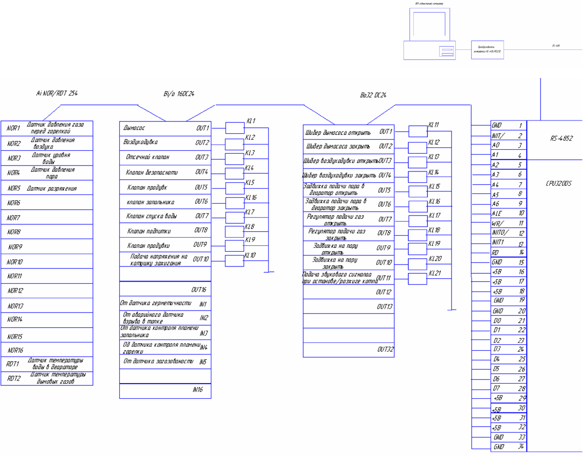
In accordance with the operating technology of the steam boiler and the technical data of the Microcont-R3 automation system, we accept the following modules for installation:
MP-320 processor module;
discrete input/output module - Bi/o16 DC24;
Bo32DC24 discrete output module;
analog input module - Ai-NOR/RTD 254;
To ensure control over the operation of boiler units, the controllers are connected to a local network via the RS-485 protocol, at the top level of which there is an IBM compatible computer with Windows installed and the STALKER program designed for collecting data, monitoring and managing the automation system.
The stalker system provides:
Control of unauthorized access to station management and information;
Control of input/output of field level data coming from the local network;
Operation of the monitoring and control system in real time;
Converting field level signals into system control point events;
Dynamic integration of new devices during system operation;
Signaling a malfunction of the local network or data collection devices and recording unreliable data;
Possibility of redundant communication channels and protection against failures;
Possibility of computer backup;
Ability to connect clients to a workstation via the EtherNet network;
Field level data processing;
Dynamic control (on/off) of data processing;
Translation of field-level hardware values coming from the local network into physical values of control points;
Monitoring the reliability of control point values;
Analysis of the alarm level of control points;
Calculation and analysis of control point values according to specified control algorithms, ensuring the implementation of mathematical, logical, and special functions;
Registration;
Dynamic control (on/off) registration; Continuous recording of the sequence of events of all control points;
Continuous recording of trends in average values of analog data over wide time ranges;
Registration of unforeseen or planned situations for subsequent analysis using an uneven time scale;
Registration of the history of the technological process and its long-term preservation in the archive.
Graphical user interface
Operational representation of the process in detailed drawings, allowing you to observe and intervene in ongoing processes in real time. The pictures are placed on consoles and panels, presented in the form of standard Windows windows. Control of windows of consoles and panels (opening, closing, working with menus, entering texts, moving, etc.) is carried out using the standard Windows interface. Remote control is a graphical window form, activated by a function key from the alphanumeric keyboard or a graphic key from another remote control. or panels.
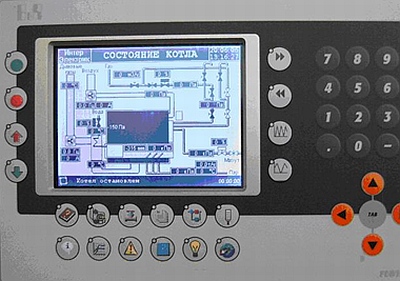
Panel - a graphic window form that belongs to the remote control according to technological or some other characteristic and can only be activated by a graphic key from the remote control or another panel (Fig. 8)
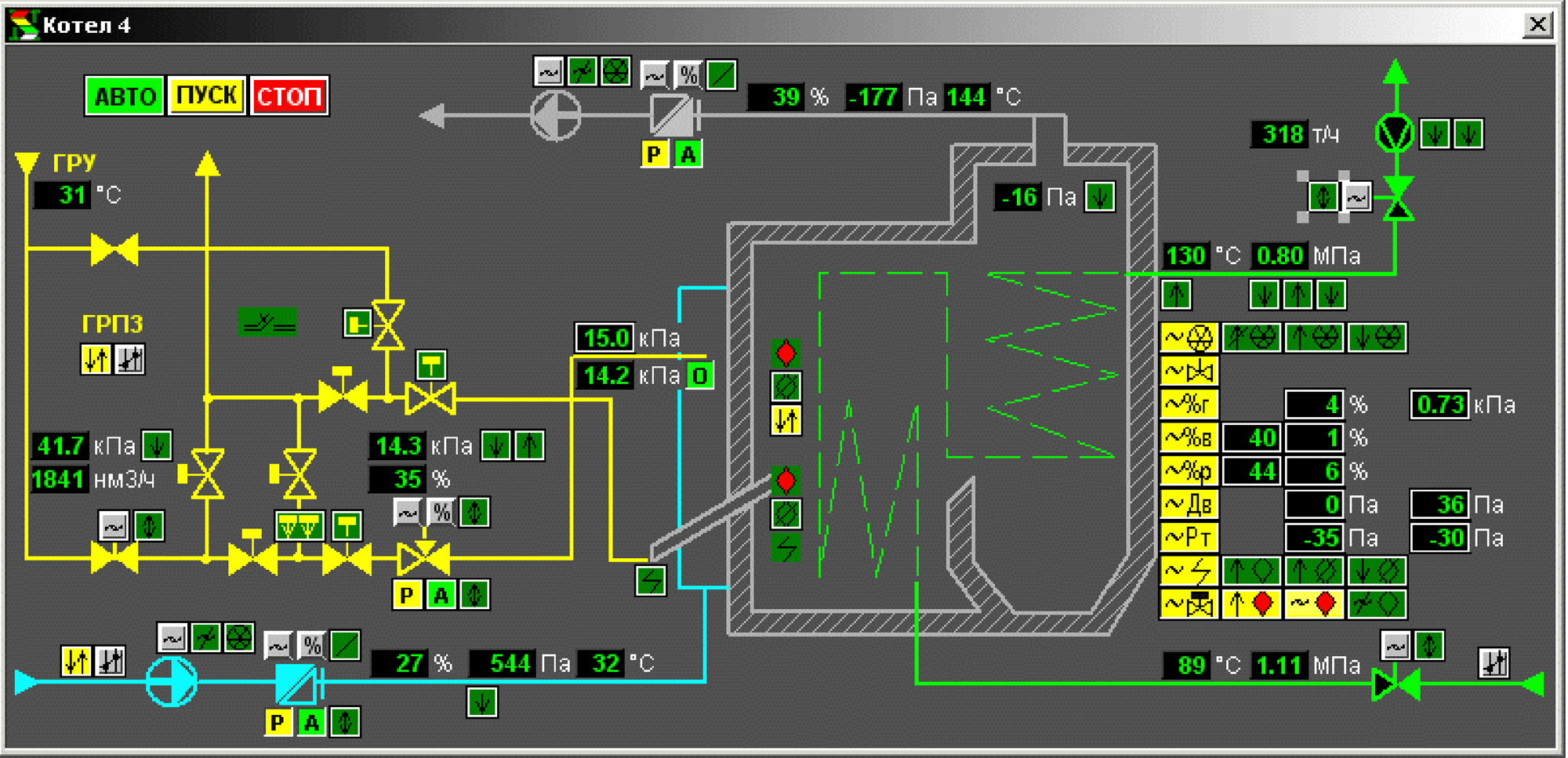
Fig.8 Mnemonic diagram of the operation of a steam boiler
Presentation of trends in average values of analog data on panels in the form of histograms and graphs.
Presentation of lists of events and current states of control points on panels.
Alarm about deviations from the normal flow of the process.
Prints system data and graphical forms displayed on consoles and panels.
Support of existing and design of new graphic panels during system operation.
4. SENSORS USED IN THE STEAM BOILER AUTOMATION SYSTEM
To measure the water level in the upper drum, we use explosion-proof radio wave level meters UR 203Ex designed for non-contact continuous measurement of the level of liquid, bulk and lump products in process tanks, tanks, silos, bunkers, etc. stationary objects, as well as for exchanging information with other technical means of automated control systems (ACS). The operating principle of the level gauge is based on measuring the propagation time of a radio signal emitted by the device to the surface of the controlled environment and back. As a result of signal processing, digital (code) and current output signals are generated, proportional to the current value of the measured level.
Possibility of dismantling the measuring part of the device without depressurizing the container.
There is no need to double-check the readings during routine maintenance due to the linking of the radiation frequency to the frequency of the reference generator.
Setup and calibration are carried out remotely via a digital communication interface.
TECHNICAL DATA
Measuring range:
-UR 203Ex-30 0.5 -30 m
Controlled environment parameters:
- pressure up to 1.6 MPa
-temperature from -40 to +150 °C
Supply voltage DC or AC 24 ± 2.4 V
Power consumption, VA, no more than 5
Output signals
-digital according to RS 485 standard (Modbus protocol)
-current 4 -20 mA
- load resistance, no more than 0.5 kOhm
Length of cable communication line for transmitting output signals up to 1000 m
Limits of permissible basic error ±1 cm
IP65 degree of protection against dust and water provided by the enclosure
Explosion protection:
-type of explosion-proof enclosure
-marking 1ExdIIBT3
Reliability indicators:
MTBF, not less than 105 hours
average service life 14 years
To measure pressure, we use devices of the Sapphire-22 series, in which a sapphire membrane with sputtered silicon resistors is used to convert the force of pressure into an electrical signal.
The main advantage of Sapphire-22 transducers is the use of small deformations of the sensitive elements, which increases their reliability and stability of characteristics, and also ensures vibration resistance of the transducers. With careful temperature compensation, the maximum error of instruments can be reduced to 0.1%.
To measure the fuel pressure in front of the burner we take Sapphire-22MP-Vn-2050-09 with characteristics:
materials – Titan VT-1-0
weight - 2.5kg
output signal - (4-20) mA
To measure pressure in a gas pipeline in the mode of checking the tightness of valves, we use Sapphire-22MP-Vn-2050-09 with the characteristics:
maximum absolute pressure - 0.25MPa
safety - explosion-proof enclosure
materials – Titan VT-1-0
limit of permissible basic error - 0.1
weight - 2.5kg
connection circuit - 2-wire
output signal - (4-20) mA
To measure vacuum, we use Sapphire-22MP-Vn-2350-09 with the following characteristics:
maximum absolute pressure - 40 kPa
safety - explosion-proof enclosure
materials – Titan VT-1-0
limit of permissible basic error - 0.1
weight - 2.5kg
switching circuit - 2-wire output signal - (4-20) mA
To measure the temperature of fuel oil and exhaust gases, we take thermal converters from those offered complete with an analog signal input module (Table 2).
To ignite and control the presence of flame in the boiler furnace, we use a flame control device Fakel-3M-01 ZZU.
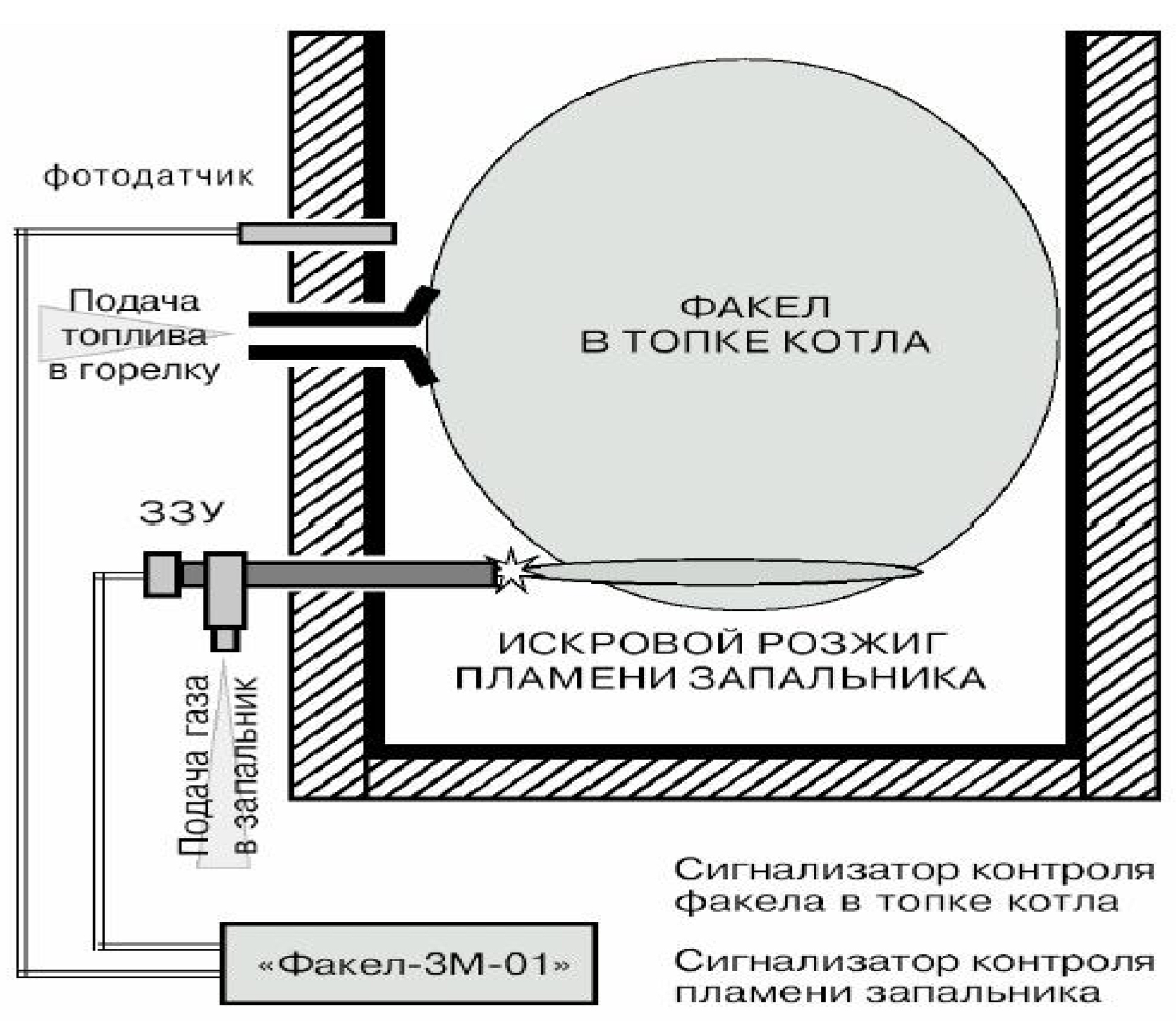
This device is designed to control the presence of a torch in the boiler furnace and for remote ignition of burners using an ignition device with an ionization sensor of its own flame.
Torch-3M-01 consists of a signaling device, a photosensor, an ignition device with an ionization sensor and a spark ignition unit. The spark ignition unit at the output provides a pulse voltage of up to 25 kV, sufficient to ignite the gas supplied to the ignition device.
To ensure safety in the event of the possible appearance of natural or carbon monoxide, we will install an automatic gas control system SAKZ - DN40.
This modular automatic gas control system SAKZ-M is designed for continuous automatic monitoring of the content of fuel hydrocarbon (CnHm; hereinafter referred to as natural) and carbon dioxide (carbon monoxide CO) gases in indoor air with the issuance of light and sound alarms and shutting off the gas supply in pre-emergency situations. Scope of application: ensuring the safe operation of gas boilers, gas heating devices and other gas-using equipment in boiler houses, gas pumping stations, industrial and domestic premises.
The use of the system significantly increases the safety of operation of gas equipment and is necessary in accordance with the prescriptive documents of Gosgortekhnadzor.
5. COST OF AUTOMATION

The equipment installation will be carried out by a team of 4 people with a salary of 15,000 rubles/month. and a period of 2 weeks (coefficient for installation 5.71 = 4 (person) * 0.5 (2 weeks or half a month) / 0.35 (wage fund)). Consequently, the amount of equipment installation will be 85,714 rubles. Setup and commissioning must be carried out within 1 month, consisting of 2 people with a salary of 35,000 rubles (coefficient for commissioning (here wages are time-based per month) 5.71 = 2 (persons) * 1 (4 weeks or 1 month )/0.35(wage fund)). And in the end it will be 200,000 rubles. This system can be serviced by 1 operator with a salary of 30,000 rubles. Delivery of the object to Gosgortekhnadzor 85,714 rubles (coefficient for approval at Gosgortekhnadzor (here wages are piece-rate for the result) 2.86 = 1/0.35 (wage fund)).
6. BRIEF DESCRIPTION OF THE OPERATION OF THE STEAM BOILER AUTOMATION SYSTEM.
Automation of the operation of a steam boiler is carried out according to four parameters: maintaining steam pressure at a given level, maintaining the gas-air ratio, maintaining the vacuum in the boiler furnace and the water level in the drum.
Pressure regulation occurs by changing the fuel supply to the burner. Technically, this is accomplished by changing the position of the damper equipped with an electric drive. As a result, a change in fuel pressure occurs, which is recorded by a pressure gauge, the force action of which is converted into an electrical signal and fed to the input of the analog signal input module. There, this signal is digitized and, in the form of a code combination, enters the central processor module and is processed according to a pre-programmed algorithm. And since we have a requirement to maintain the gas-air ratio within 1.1, a signal is sent to the discrete input-output block to change the position of the blower gate until the specified ratio is achieved.
This ratio of gas and air pressure is selected experimentally during commissioning.
The vacuum in the boiler furnace is monitored independently and maintained at a level of 5 mmHg. pillar
The water level in the drum is also maintained by opening or closing the make-up water valve.
The boiler is ignited in the following order:
— first, the boiler furnace is ventilated with the smoke exhauster and blower turned on, so that the gas-air mixture does not explode;
— then, with the safety valve and shut-off valve closed, the absence of gas pressure is monitored (the pressure sensor is open) for 5 minutes;
— the shut-off valve opens for 2 s;
— with the safety valve and shut-off valve closed, the presence of gas pressure is monitored (the pressure sensor is closed) for 5 minutes;
— the safety valve opens for 5s;
— the absence of gas pressure is monitored (the pressure sensor is open);
— after checking the tightness of the gas pipeline, a signal is sent to open the pilot burner valve and pulses are sent to the ignition coil. When the pilot burner torch is ignited, a stable signal is sent from the pilot flame control electrode, as a result of which the main burner valve opens and the boiler is put into operating mode. Also, this automation system ensures that the fuel supply is stopped in the following emergency modes when water is lost; when the smoke exhauster stops; when the blower stops; when the pressure in the fuel line decreases; in case of a gas explosion in the boiler furnace; when the gas sensor is triggered; with a sharp increase in steam pressure.
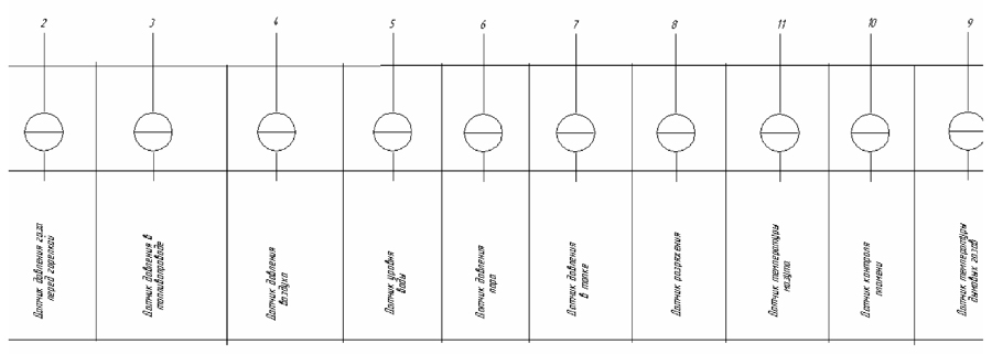
7. SENSORS AND AUTOMATION CONNECTION DIAGRAMS

8. LIST OF REFERENCES USED
1. http://www.referat.ru/pub/item/21163 (Sopov S. “Automation of the steam boiler DKVR 20 - 13 2005”, Perm, Perm State Technical University, Department of Electrification and Automation)
2. http://www.syst.ru/mkr2/charact.htm#ppkp (Description of the Microkont-R3 controller)
3. http://www.ump.mv.ru/f-3m.htm (Description of the device for monitoring the presence of a torch in the furnace of the Fakel-3M boiler)
4. http://www.manometr.com/ (Description of Sapphire-MP sensors)
5. http://www.energiatlt.ru/ener_2.htm (Description of radio wave level gauge UR 203Ex)
6.http://eurogaz.ru/index.php?option=com_content&task=view&id=9&Itemid=36 (Price list of gas control systems)
7. http://home.overta.ru/users/cit/SAKZ/SAKZ.html (Description of the gas control system)
8. http://www.syst.ru/mkr2/in_out.htm#ainor-rtd (Description of modules Bo32DC24, Ai-NOR/RTD, 254 Bi/o16 DC24)
Modern technologies in the field of heating installations allow a person to exercise minimal control over the process of their operation. Boiler automation is a boiler control system that regulates its operating mode. Namely, temperature conditions, heat transfer, etc. Their schemes may be different, but absolutely all such devices are economical and easy to use.
Rice. 1Installation Features
Automation of boiler installations performs the following tasks:
- Controls the process of turning on and off boilers in the equipment system (start/stop), auto-ignition;
- Connecting backup equipment (if it is in the diagram) - if the main boilers stopped for some reason;
- Adjustment of coolant characteristics;
- Adjusting the power of equipment (boilers in the circuit);
- A protective function that is triggered when boilers fail;
- Energy saving during boiler room operation;
- Notifies about an emergency situation by turning on the alarm (there may be different circuits: light, sound);
- Monitors the readings of indicators and sensors that determine temperature (air and coolant), water pressure and pumps;
- Preventing boiling of the coolant;
- Preventing the system from freezing.
Automatic equipment minimizes the human role in managing a heating boiler room. There are systems that, in the event of an emergency, send an SMS notification to the operator of this equipment.
All modern heating installations are equipped with automatic control. Inexpensive ones have a simple automation system. This implies manual adjustment, that is, programmed on/off of the boiler. And expensive units with the most modern automatic control system can be programmed to reduce the temperature at a certain time of day, supply hot water at a set temperature, etc.
Automatic Installation Security
One of the main functions of automatic installations is to ensure the safety of users and boiler equipment.
An alarm, which means the occurrence of an unexpected situation in the installation, notifies about:
- Leakage of gas or other fuel;
- An increase or decrease in pressure (gas, water, steam) in the system;
- Boiler accidents;
- Carbon monoxide emissions;
- Fire safety violations.
The boiler automation circuit is designed in such a way that the operator can control it remotely. At the same time, he can view the fault diary, thanks to which service center workers can easily identify all failures in the system. It is also possible to control the installation using your phone. For this, a special code is used, when dialed, the automation switches to another operating mode (preset).
Design (diagram) of the installation
Boiler automation is divided into several levels. These include:
- Level I – the package includes thermostats and regulators that maintain the air temperature, as well as the possibility of a heating schedule.
- Level II – to all the functions of the first category, equipment power regulators are added, as well as its controllers and the possibility of cascade connection and its regulators.
- Level III – has a control panel that displays all readings from sensors and regulators.
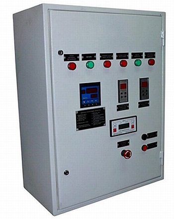 Rice. 2
An automatic boiler station is installed in a special metal cabinet.
This scheme includes:
- Controllers that are programmable;
- Secondary power supplies;
- Uninterruptible power supply circuit;
- Hub;
- Operator panel;
- Switching equipment;
- Computer.
 Rice. 3
Work process
Boiler automation can control boilers with cascade connections. When a boiler room operates with a cascade scheme, the load is light and the service life of the installation increases. Since the automatic control system turns on the boilers and pumps alternately. With all this, this heating system is very economical and provides the desired temperature in the room.
Depending on the season, the automatic control installation turns on the required number of boilers. Automation can determine the optimal air temperature and heating mode without operator intervention. The installation is equipped with valves, the operation of which is regulated automatically. For example, the circuit contains a mixing valve and a servo drive valve. These valves operate in a predetermined mode, thereby guaranteeing fuel and energy savings, as well as a comfortable air temperature.
If such boiler automation is installed in production, then it is possible, in order to achieve savings, to set a specific schedule for heating and hot water supply. On weekends and holidays, as well as at night, the air temperature can be reduced, and there may be no hot water at all. Such measures save up to 40% of fuel.
Modern microprocessor control units have more complex circuits. Thanks to them, you can set different temperatures in different parts of the heating system. That is, in different circuits, for example, a radiator circuit, a heated floor circuit, etc. Some modern installations can control 15 independent circuits simultaneously. And at the same time, adjust the mode to weather conditions.
Thanks to new automatic installations (schemes), boiler rooms are becoming more environmentally friendly. This is due to the reduced amount of fuel consumed. And of course it should be noted that the circuitry of this equipment contains additional powerful filters.
Safe operation of boiler plants and effective management of the dispatch process is achieved through automation of systems and modern information technologies. Improving old boiler houses or replacing them with new ones makes it possible to eliminate the problem of a failed system and reconstruct outdated automation.
Boiler room automation system capabilities
It provides:
- automatic regulation of coolant parameters;
- starting, stopping, control and power regulation;
- turning on the backup boiler if the worker stops;
- automatic control of pumping devices;
- power supply to boiler circuits;
- implementation of energy-saving algorithms for the boiler room;
- emergency alarm operation and transmission of signals to the upper level.
Automation of boiler plants based on equipment from the MZTA plant is the key to high-quality and prompt service. This is a warning about emergency situations, reducing the time to find and eliminate an accident.
It is possible to reduce energy costs, equipment downtime, repair costs, increase service life and ensure optimal operating conditions thanks to automated systems.
Functions of the boiler room dispatch system
Thermal boiler houses can be improved by introducing a dispatch system. It allows you to remotely receive data and control the operation of the boiler room. With its help, it becomes possible to control the technological process in real time, maintain an alarm log and record the actions of system users.
Consequently, dispatch improves the quality and speed of boiler room service, allows you to respond to emergency situations in a timely manner, reduce equipment wear and increase employee productivity.
You can control the automated boiler room from a central control center. This makes it possible to reduce the number of service personnel.
“Forewarned is forearmed!”
GSM boiler room remote control system
A boiler control system in its most general form is a systematized set of means of influencing a controlled object in order to achieve certain goals by this object.
In our case, the “controlled object” is a boiler, burner, pumps, pipelines, a boiler for preparing hot water, radiators, “warm floors”, etc., that is, the heating system as a whole. The “goal of control” is, on the one hand, to maintain the set temperature in the house, obtain a sufficient amount of hot water, that is, to create conditions for the most comfortable living, and on the other hand, to reduce energy costs and extend the service life of equipment.
I would like to note right away that comfort and economy are incompatible concepts, but the automation of boiler rooms, furnaces, and individual heating units allows them to be combined. What is it automation of boilers and heating systems? First of all, let’s focus on boiler automation itself. The mandatory set includes protection and control organs.
Boiler safety automation must include an overheating protection thermostat. Also optionally installed are relays for protection against a decrease or increase in coolant pressure, devices for monitoring the fullness of the boiler block with coolant, a gas pressure control relay (if the boiler is gas), on atmospheric gas boilers it would not be superfluous to install an exhaust gas control relay, also known as a reverse sensor traction. All these elements are designed to prevent the operation of boiler equipment in unacceptable modes, both from the point of view of the safety of the heating system and the safety of the owner of the house, cottage, cottage, and enterprise personnel.
Basic automatic control, as a rule, consists of one single control thermostat, which sets the maximum boiler water temperature. Plus an on/off button, a pressure gauge and a thermometer. All! But there are people who sincerely believe that this is enough. There are two possible options here: for comfortable use of hot water, the boiler constantly operates at maximum temperature and you have to open the windows in the house (the so-called “window control”, in Germany they just don’t shoot for this), which, among other things, increases bills for gas, diesel fuel, firewood, coal, or, in order to save money, they set the thermostat to minimum, “driving” the boiler into condensation mode of operation, thereby hastening its quick death from corrosion. The funniest and saddest thing about this is that the fuel economy is miserable. It turns out that with completely manual control, in most cases neither comfort nor efficiency is achieved.
Hot water preparation module control system
The first step in heating automation is to include a hot water preparation module in the control system and install a room thermostat. The DHW preparation module monitors the water temperature in the boiler and, when it drops, commands the boiler and the boiler loading pump to turn on. As a rule, the heating pump is turned off while hot water is being prepared. The priority of DHW preparation prevents overheating of heating devices and allows the use of a lower power boiler. A room thermostat controls the temperature in the room and commands the boiler to turn on only when the temperature in the house drops below the set value.
The disadvantages of room temperature control systems include, firstly, the low accuracy of room thermostats (delta is 2 - 4 degrees), secondly, the boiler is not protected from operation in condensation mode, and thirdly, adjustment in such systems is carried out precisely according to room temperature, that is, the boiler turns on when the enclosing structures have already cooled down and the temperature in the house has begun to drop. In technical terms, a continuous oscillatory process occurs in the heating system. And constant freezing/thawing cycles have not benefited any wall yet.
Weather-compensated boiler automation
The most common control systems today are weather-dependent automation of boilers and heating circuits. Weather-dependent boiler automation, as the name suggests, monitors the temperature of the outside air and, depending on it, calculates what temperature the coolant needs to be supplied to the heating devices to maintain the set temperature in the room. When setting up such automation, a number of parameters are specified that are specific to a given object and the system adapts specifically to it. In principle, a well-tuned automatic boiler control system does not require human intervention, but for more accurate operation it would not be amiss to install a room temperature sensor. The main difference between a “sensor” and a “thermostat” is that it monitors not just the temperature in the room, but the dynamics of its change. This allows boiler automation to “predict” the future state of the system and take preventive measures to stabilize the temperature in the house.
If there are several circuits that must operate according to their own programs with different coolant temperatures, it makes even more sense to assign the control task to automatic control systems. Or hire a professional heating engineer as your boiler room operator.
Heating control methods can be divided into the following types:
- Fully manual control by changing the set temperature of the coolant in the boiler. The only advantage is the minimal initial costs. Disadvantages include increased fuel consumption, difficulty achieving comfort and the need for constant presence of maintenance personnel. The use of thermostatic heads on radiators somewhat improves living comfort, but worsens the working conditions for pumps and the boiler.
- Boiler control systems with priority hot water preparation and manually adjustable coolant supply temperature. The comfort of preparing hot water increases and it is possible to adjust the room temperature using the room thermostat. The disadvantages include the low accuracy of the vast majority of room thermostats, still increased fuel consumption and the lack of direct consideration of weather factors, which adversely affects the structure of the house as a whole. Also, in particular, in such boiler control systems it is almost impossible to competently organize such an almost mandatory element for a modern home as a “warm floor”.
Automated weather-dependent control systems for boilers and heating circuits do not have the disadvantages inherent in manual control systems. Capable of automatically maintaining the currently required temperature of the coolant in the boiler and in each heating circuit connected to the control system. When calculating, they are guided by the outside air temperature, the set and actual room temperature (if we are talking about a heating circuit), and the set program. As a rule, such control systems can be combined into a single system via a data exchange bus, which allows you to create a cascade of boilers and increase the number of heating circuits almost indefinitely. Due to the fact that the control of heating circuits and boilers is centralized, fuel consumption is optimized and, all other things being equal, is reduced by 15-20% compared to manual control systems. The only “disadvantage” of automatic control systems is their initially high cost. But you need to understand that these are capital costs. And operating costs will be significantly lower, and in the foreseeable future, savings on fuel and electricity will compensate for equipment costs.
Thus, when choosing a control system for your boiler, you need to answer a number of questions: the required level of living comfort, the number of heating circuits, the presence of “warm floors”, the presence of a heat exchanger for the pool, ventilation, the expected service life of the heating equipment and, based on these factors, conduct a brief technical and economic analysis of heating equipment control options. According to the roughest estimates, for a house with an area of about 500 square meters, heated by a diesel boiler, the cost of an automatic weather-compensating control system is equal to one to two months of diesel fuel costs for manual control. But the choice is always yours!
Head of the service department Zhilin M.V.
Analysis of modern boiler room automation systems
Borisov G.B., Ph.D. tech. sciences
OJSC "Moscow Thermal Automation Plant"
Currently, the existing fleet of boiler houses is being actively updated and modernized, but the number of facilities requiring reconstruction is still large. Automation systems are in a particularly depressing state.
In many regions of Russia, the wear and tear of gas equipment, gas-using installations, and boiler room automation equipment is 60...80%, and for some items, such as automatic security systems, in some cases it can approach 100%.
Since the duration of operation of the equipment has significantly exceeded the planned service life (for automatic safety systems several times), the issue of further trouble-free operation of the equipment becomes especially important. The problem is aggravated by the lack of spare parts and components, which makes it extremely difficult to maintain equipment in working condition. Of course, the optimal solution to the fate of worn-out equipment would be its complete replacement with modern equipment, however, due to limited funds, this issue is often resolved at minimal cost: only what can no longer work is changed.
To establish the possibility of further operation of the technical equipment of the boiler room, it is necessary to carry out diagnostics of the equipment. To determine the condition of boiler fittings (sections, pipes, valves, etc.), there are several methods, for example, fluoroscopic, which makes it possible to predict the performance of the specified equipment with a reasonable degree of probability. The situation with automation equipment is more difficult. Boiler automation, introduced back in the 70-80s of the last century, fundamentally does not meet the requirements of today's SNiPs, PBs and safety instructions.
Many types of automation equipment are obsolete and are being discontinued. The requirements for monitoring the tightness of gas blocks, automatic (without operator participation) ignition of burners and boiler, and automatic control of parameters are not met. Such systems often operate in manual mode, which is absolutely unacceptable.
Thus, even if the thermomechanical part of boiler houses can (with positive diagnostic results) continue to be used, the electronic automation devices definitely need to be replaced. The lack of automatic security or the use of outdated designs often leads to serious consequences.
Economic and social effect of introducing automation equipment
In modern market conditions, we can talk about the economy of security. As a result of reducing the accident rate of equipment equipped with safety automation, real benefits can be obtained. Money is saved on fines, on repairs of equipment and buildings damaged by accidents, and on compensation for injured personnel. The human losses or loss of ability to work of people affected by accidents remain irreparable. .
Thanks to the use of modern control technologies (intelligent burners, automatic PID control of key technological parameters, frequency control of the smoke exhauster and fan, correction of the fuel-air ratio based on the oxygen content in flue gases, etc.), a reduction in fuel and electricity consumption is achieved. In the context of constantly rising energy prices, lo provides a fairly quick payback for new automation equipment.
The service life of process equipment can be increased with the help of improved controls (for example, automatic boiler start-up with a soft warm-up function) and modern safety automation that prevents emergency situations leading to accelerated wear of the equipment.
Automatic regulation of basic technological parameters and the use of the latest microprocessor-controlled burners allow optimizing the combustion process and reducing harmful emissions of nitrogen oxides NOx. Compliance with environmental standards leads to savings on monetary fines.
With integrated automation of boilers, the number of labor-intensive manual operations (for example, starting a boiler manually) is radically reduced, and it becomes possible to control the operation of boiler rooms without permanent maintenance personnel. Previously, it was necessary to hire a staff of emergency dispatchers who would work in shifts around such fire pits. When organizing a remote central control room, it becomes possible to quickly monitor the condition of an entire network of boiler houses connected to it and, if necessary, dispatch mobile teams to troubleshoot problems with specific equipment. This makes it possible to reduce the number of emergency dispatchers and ensure high responsiveness to emergency situations.
Goals and objectives of automation of steam boilers
The first and most important goal of automation is to protect fuel-using and boiler equipment from emergency situations and ensure the safety of operating personnel. That is why this class of devices is often called simply “safety automation”. All other functions are undoubtedly important, but are of a secondary nature. An analysis of accidents in boiler houses and other gas-using facilities shows that they mainly occur during ignitions, and their cause is the so-called human factor. Security automation should eliminate such situations.
The second important goal of automation is the implementation of energy-efficient control algorithms: maintaining optimal vacuum, gas-air ratio, steam pressure and water level. A steam boiler is a power plant, during the operation of which interconnected technological parameters change with high dynamics. The process control system allows you to optimize these parameters based on economic, environmental, ergonomic and other indicators. Therefore, the main tasks of developers, designers and adjusters when creating the described system are:
- ensuring safe operating conditions of boilers;
- reduction of fuel and electricity costs;
- increasing the service life of process equipment;
- reduction of harmful emissions into the atmosphere;
- improving working conditions for operating personnel.
Automation cabinet functions
An automated thermal process control system, implemented in the form of an automation cabinet, allows you to solve the following tasks:
- automatic preparation of the boiler for ignition;
- automatic ignition of the boiler burners with transition to minimum power mode;
- load control and optimization of the gas-air ratio of each of the boiler burners;
- control of the thermal regime of the boiler (regulation of vacuum in the furnace, air flow in front of the burner, water level in the tank);
- automatic boiler shutdown (regular and emergency);
- protection, alarm and blocking of the boiler in case of malfunctions;
- providing operational process personnel with information about the parameters of the thermal regime and the condition of process equipment (including by exchanging information with the dispatch station).