n1.doc
Novosibirsk State University of Architecture and Civil EngineeringDepartment of Metal and
wooden structures.
Course Project.
“Structures made of wood and plastics.”
Completed by student gr.411
Amzorova O.V.
Checked:
Shvedov.V.N.
Novosibirsk 2004.
Choice design diagram. 3
1. Calculation of the covering panel. 3
1.1.Layout of the working section of the panel. 4
1.2. Collection of loads on the panel. 5
1.3. Design characteristics of materials. 5
1.4. Geometric characteristics of the panel section. 5
1.5. Checking the panel for strength. 6
2.Static calculation of the farm. 7
2.1.Calculation of truss elements. 8
2.2. Calculation of nodal connections. 11
3. Glued stand of a single-span frame. 16
4. List of references. 21
Design assignment.
Design and calculate a truss with a span of L= 12 m to cover a heated industrial building and a pillar h = 4.5 m. The spacing of the trusses is a=6 m.Selection of design scheme.
We accept a triangular truss. Truss height: f = 2 m. Roof angle: tg? = ;20.48°; sin? = 0.316; cos? = 0.949.
Top chord panel length: l 1-3 =  m.
m.
Brace length: l 5-11 =  m.
m.
Stand length: l 3-11 = l 1-3 tg? = 3.16*0.333 = 1.05 m.
Length of the lower chord panel: l 1-11 = m.
1. Calculation of the covering panel.
Since the building is heated, we will use an insulated adhesive plywood covering panel. The size of the panel (Fig. 1) in plan is 1.48 x 5.98 m. The cladding is made of waterproof plywood of the FSF grade, grade V/VV, according to GOST 3916-69*; ribs from main boards of the second grade. Glue brand FRF-50. Insulation – mineral slabs 8 cm thick with a synthetic binder in accordance with GOST 9573-82*. The insulation density is 1 kN/m3. Vapor barrier made of polyethylene film 0.2 mm thick.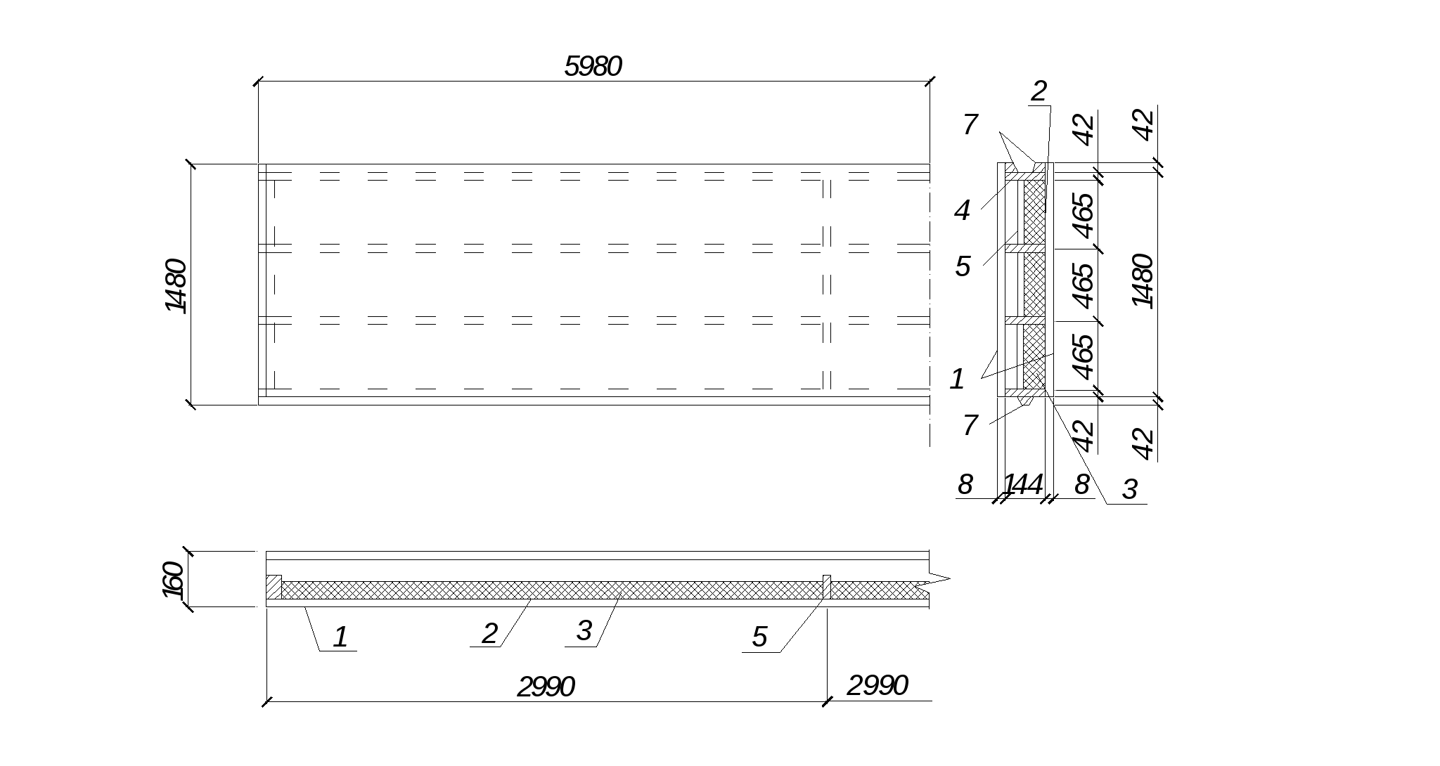
1 – plywood sheathing; =8 mm. 2 – vapor barrier; 3 – insulation; 4 – longitudinal ribs made of boards; 5 – transverse ribs made of boards; 6 – end board for attaching the panel to the support; 7 – side trapezoidal bars.
1.1.Layout of the working section of the panel.
We take the panel width b p = 1480 mm. The thickness of the plywood is 8 mm. Boards with a cross section of 50 x 150 mm are used for gluing. After four-sided milling of the rough blanks, boards with a cross-section of 42×144 are used for gluing. The direction of the fibers of the outer plywood veneers, both in the upper and lower skins of the panel, should be longitudinal to ensure miter joining of the plywood sheets and for better use of the strength of the plywood. Design span of the panelThe panel frame consists of four longitudinal ribs (Fig. 1). The spacing of the ribs is taken based on the calculation of the top plywood sheathing for local bending across the fibers due to concentrated force.
P =  kN as a beam, capped at the ends with a width of 1000 mm. Distance between ribs in c axes =
 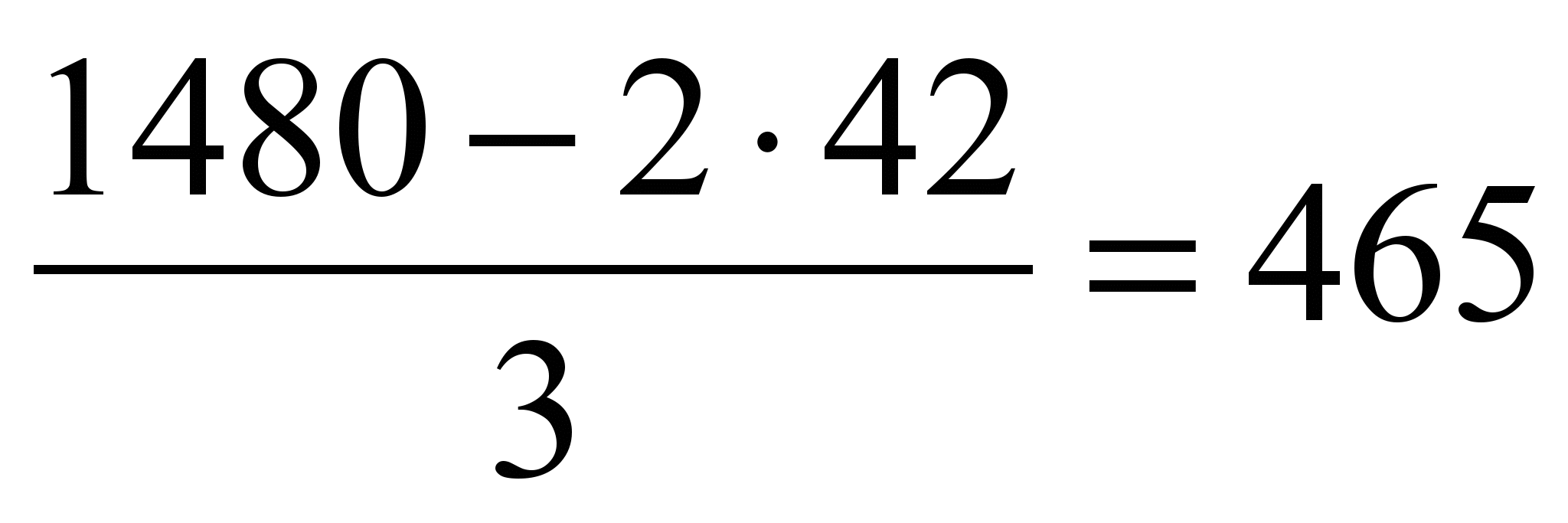 mm.
mm.
Bending moment in sheathing
M =  kN/m = 69.8 kN/mm
Moment of resistance of a 1000 mm wide skin.
W=  mm 3.
mm 3.
Bending stress due to concentrated force
? =  MPa
MPa
1.2 – operating condition coefficient for installation load.
D 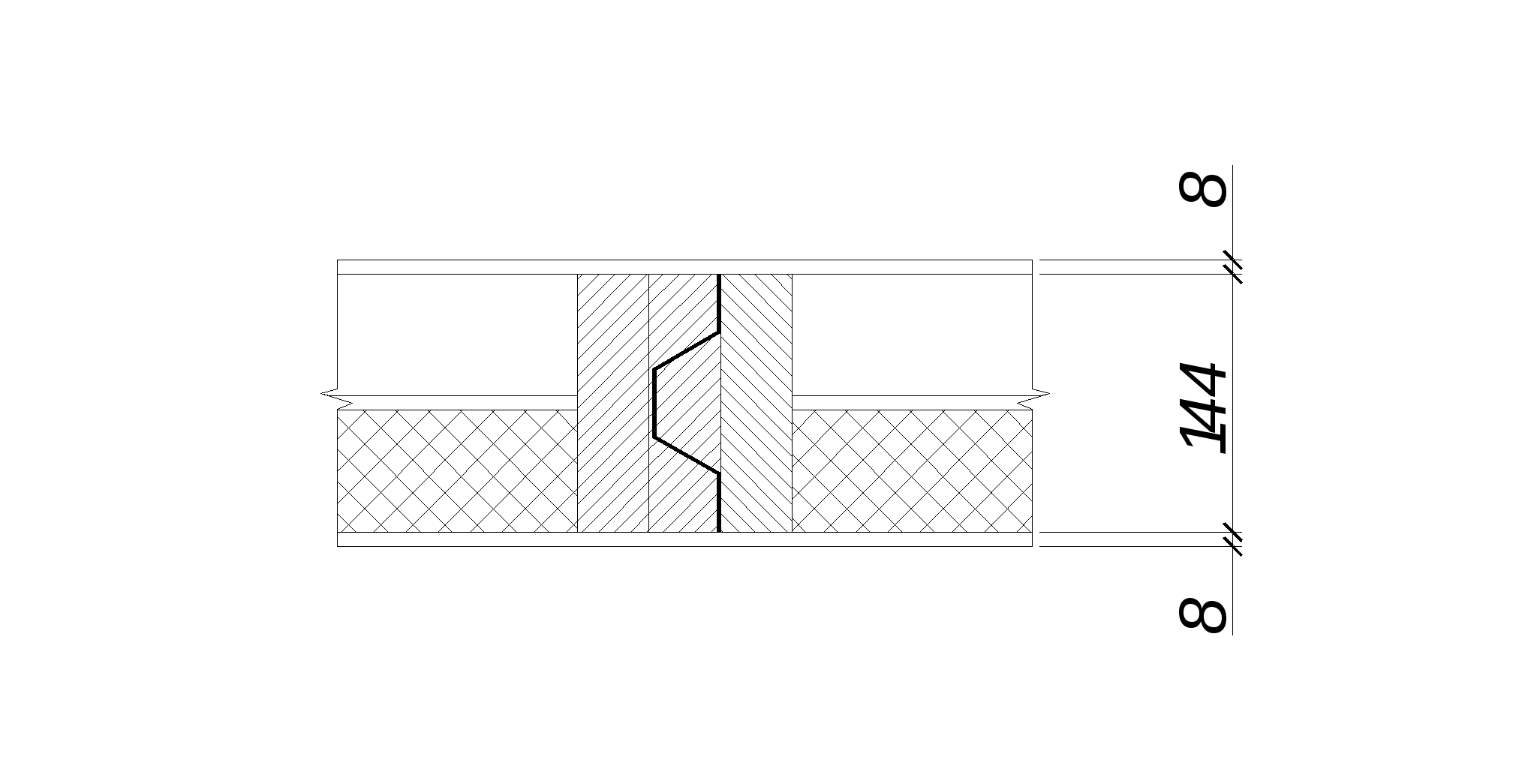 To give the frame rigidity, the longitudinal ribs are glued together with transverse ribs located at the ends and in the middle of the panel. During installation, the longitudinal edges of the panels are joined using a specially constructed tongue and groove made of trapezoidal bars glued to the outer longitudinal ribs. The tongue and groove connection thus obtained prevents vertical movement at the joint and differences in deflection of the edges of adjacent panels, even under the influence of a concentrated load applied to the edge of one of the panels.
Joining panels above the support:
1.2. Collection of loads on the panel.
| Standard, kN/m 2 | Load reliability factor | Calculated, kN/m 2 |
|
| Covering: three-layer roofing felt carpet. | 0,09 | 1,3 | 0,12 |
| Plywood grade FSF 2·0.008·7 | 0,112 | 1,1 | 0,123 |
| Pine wood frame: longitudinal ribs including bars | |||
| longitudinal ribs 4 0.144 0.042 5/1.48 | 0,085 | 1,1 | 0,09 |
| transverse ribs 3 0.092 0.042 5/5.98 | 0,0097 | 1,1 | 0,011 |
| Insulation - mineral wool boards 0.08 0.423/0.465 1 | 0,073 | 1,1 | 0,08 |
| Vapor barrier | 0,02 | 1,1 | 0,022 |
| Constant | 0,39 | 0,446 |
|
| Temporary (snow) | 0,7 | 1,6 | 1,12 |
| Full | 1,1 | 1,566 |
Full load on 1 m panel:
normative q n =  kN/m,
kN/m,
calculated q =  kN/m.
kN/m.
1.3. Design characteristics of materials.
For FSF brand plywood, grade V/VV, seven-layer, 8 mm thick. according to table 10 and 11 SNiP II-25-80 we have: design compressive strength R fs = 12 MPa, design tensile strength R fr = 14 MPa, design shear resistance R fsk = 0.8 MPa, elastic modulus E f = 9000 MPa, design resistance bending R fi = 6.5 MPa. For rib wood according to SNiP II-25-80 we have an elastic modulus E dr = 10000 MPa.1.4. Geometric characteristics of the panel section.
Reduced design width of plywood sheathing (according to SNiP II-25-80)b pr = 0.9b = 0.9*1.48 = 1.332m
The reduced moment of resistance of the cross section of glued plywood and wood elements should be determined by the formula
 ,
,
Where y o is the distance from the center of gravity of the reduced section to the bottom edge of the skin;
I pr – moment of inertia of the section reduced to plywood:
![]() ,
,
Where I f is the moment of inertia of the cross section of plywood sheathing;
I d – moment of inertia of the cross section of the wooden ribs of the frame;
E d / E f – the ratio of the elastic moduli of wood and plywood.
1.5. Checking the panel for strength.
Maximum bending moment at mid-span:M max =  kNm.
kNm.
Stresses in stretched sheathing:
P = ![]() MPa
MPa
where 0.6 is a coefficient that takes into account the reduction in the design resistance of plywood in a stretched joint.
Calculation of stability of compressed skin:
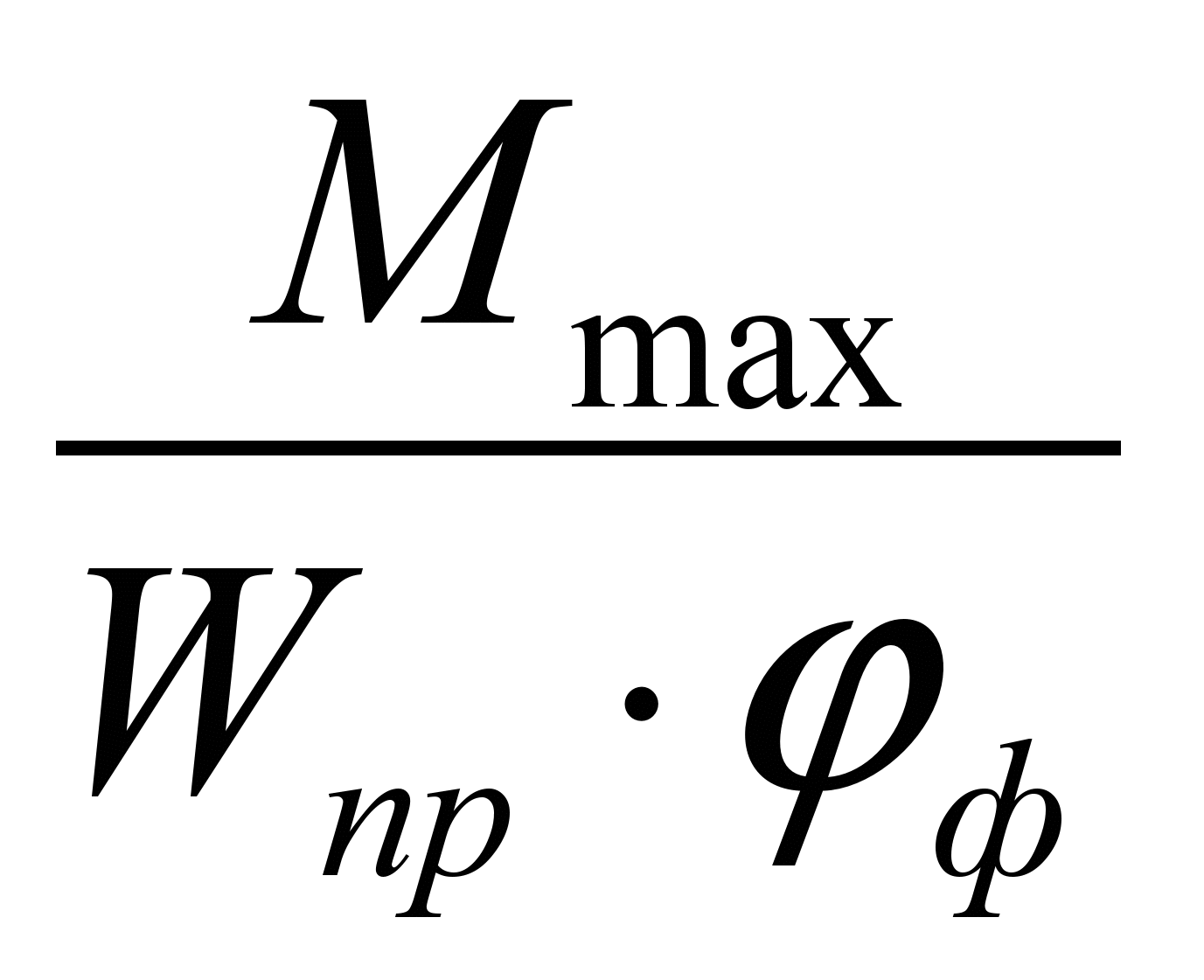 ? R fs
With a clear distance between longitudinal ribs c 1 = 0.423 m and plywood thickness f = 0.008 m
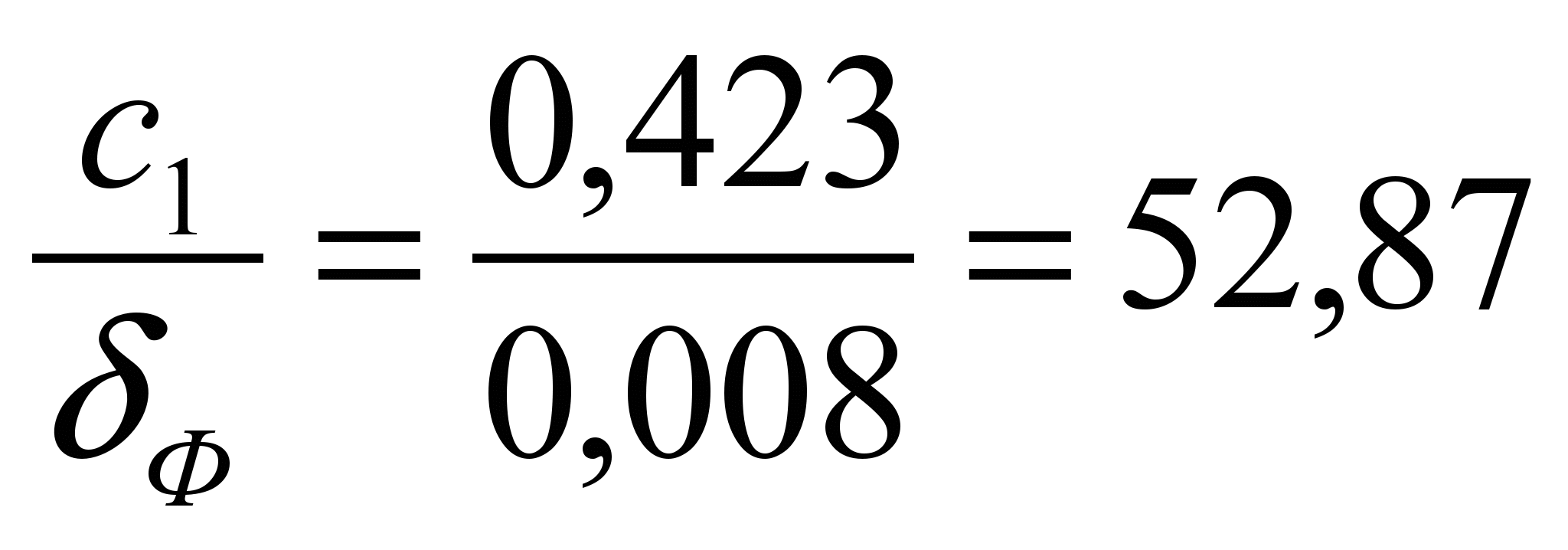 > 50,
> 50,
Then 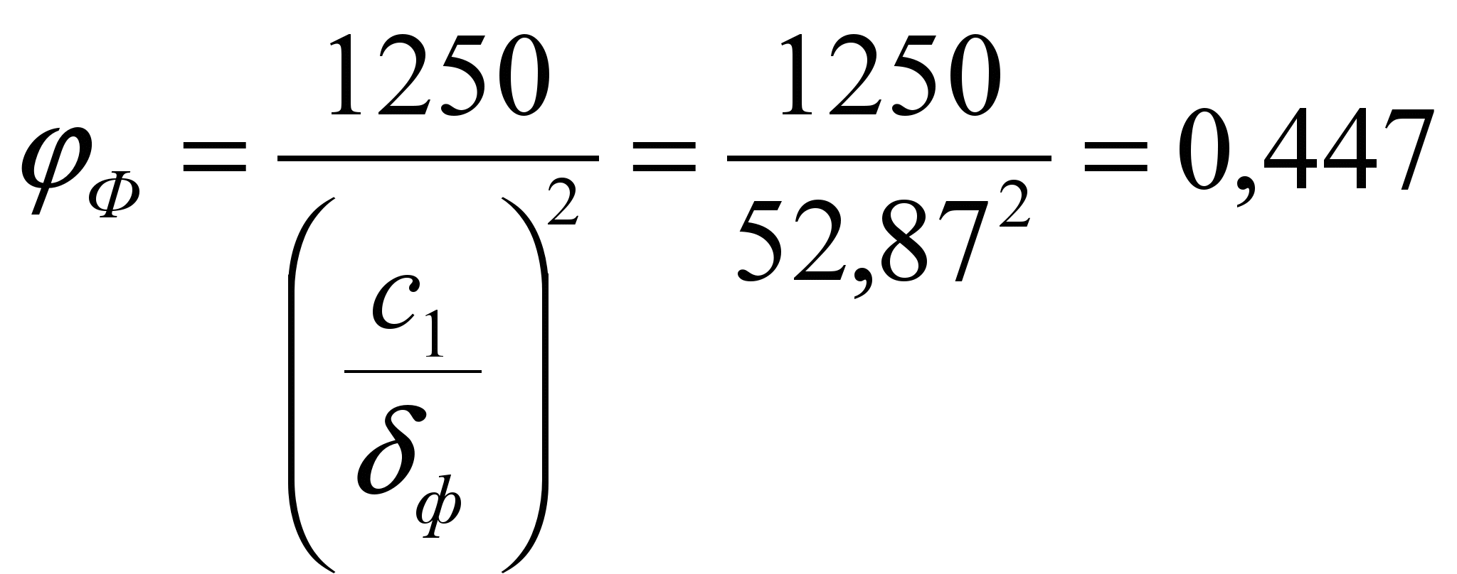 .
.
C =  MPa? 12 MPa.
Calculation of chipping on the adhesive layer of plywood sheathing is carried out according to the formula:
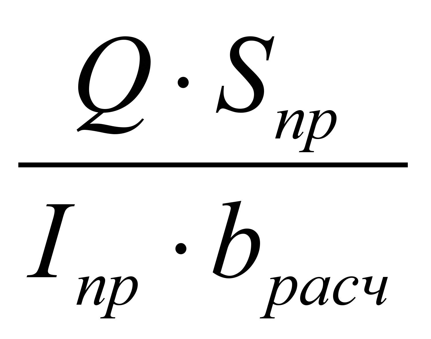 ? R fsk
The shear force is equal to the support reaction of the panel
Q =  kN.
kN.
Reduced static moment of the top plywood sheathing about the neutral axis
S pr = m 3
Design width of adhesive joint
b calculated = 4 H 0.042 = 0.168 m.
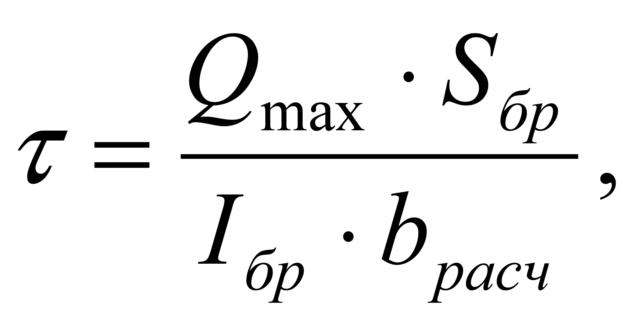
Shear stresses will be:
? =  MPa
MPa
Checking the panel for deflection.
Relative panel deflection
where 1/250 is the maximum deflection in the covering panels according to table. 16
SNiP II – 25 - 80.
2.Static calculation of the farm.
Loads per 1 m2 of building plan.The dead weight of the truss is determined at kw = 4 by the formula:


n = 1.1 – load factor for own weight.
k sw = 4 - coefficient of the farm’s own weight.
Standard value of snow load on the horizontal projection of the coating in accordance with clause 5.1. SNiP 2.01.07 – 85 is determined by the formula:
Where µ - the coefficient of transition from the weight of the snow cover of the ground to the snow load on the cover, is accepted in accordance with clauses 5.3 - 5.6. SNiP 2.01.07 -85. With a roof slope? = 20.48 0 µ = 1.
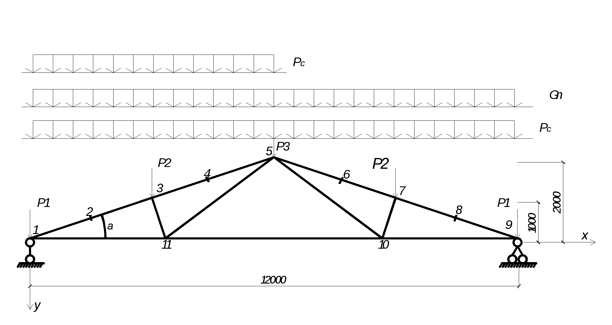
Design diagram of a triangular four-panel truss with stretched braces.
Calculation of loads per 1 m 2
building plan.
| Name of loads | Load reliability factor |
||
| Three-layer roofing felt | 0,12 | 1,3 | 0,156 |
| Plywood brand FSF | 0,112 | 1,1 | 0,123 |
| longitudinal joints | 0,085 | 1,1 | 0,09 |
| transverse ribs | 0,012 | 1,1 | 0,013 |
| Insulation - mineral wool boards | 0,073 | 1,1 | 0,08 |
| Vapor barrier | 0,02 | 1,1 | 0,022 |
| Truss dead weight | 0,054 | 1,1 | 0,0594 |
| Constant | 0,444 | 0,543 |
|
| Temporary (snow) | 0,7 | 1,6 | 1,12 |
| Full | 1,144 | 1,663 |
Calculation of load per 1 m of truss:
From constant load
G n = g H a = 0.444 H 6 = 2.66 kN/m
From snow load
P c = p H a = 1.12 H 6 = 6.72 kN/m
Calculation diagram of the truss with geometric dimensions and designation of nodes:
P 1 = P 2 /2 = 6.72 H 3/2 = 10.1 kN.
P 2 = 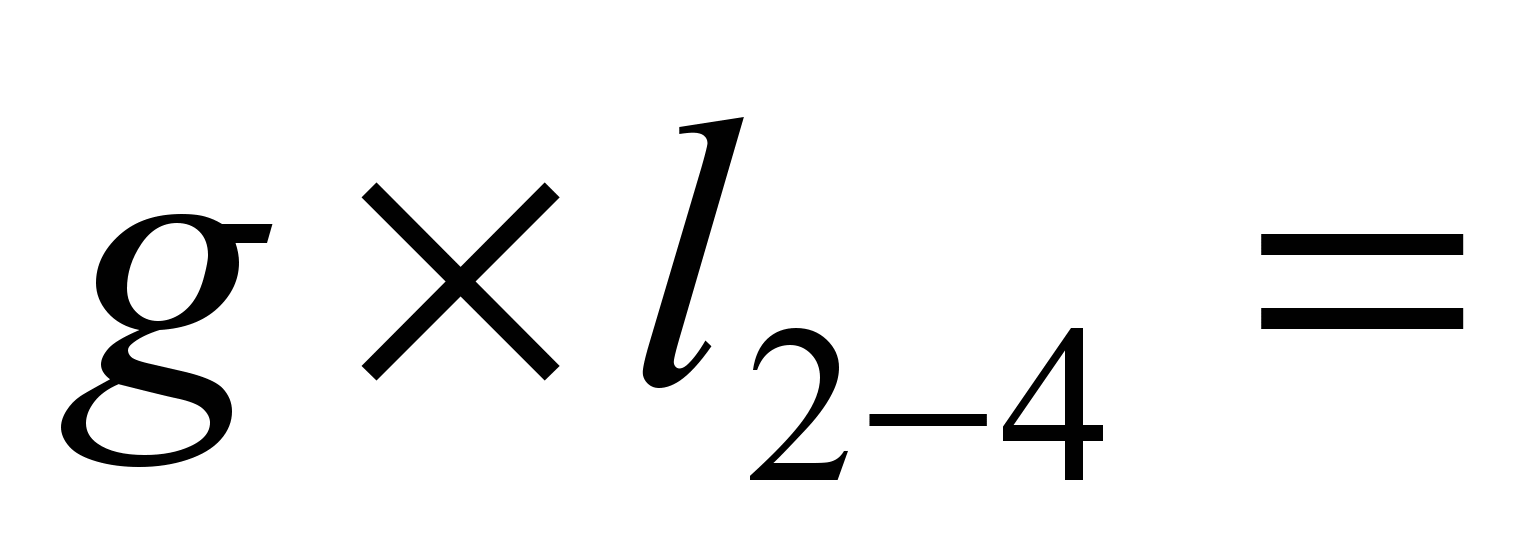 6.72 H 3 = 20.16 kN.
P 3 = 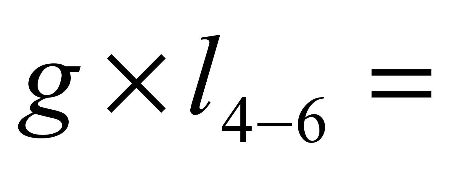 6.72 H 3 = 20.16 kN.
R 1 =  40.32 kN
R 9 = 40.32 kN
2.1.Calculation of truss elements.
Upper belt the farm takes up permanent and temporary snow loads. Maximum bending momentM max = (6.72 – 0.0594 H 4) H 3 2 /8 = 7.3 kN m
N 3-4 = 90.44 kN.
To reduce the bending moment in the truss panel, we create an eccentric application of normal force, as a result of which unloading negative moments arise in the nodes of the upper chord.
The value of the optimal eccentricity is calculated from the condition of equality of the support and span moments in the support panel of the upper chord:
Me = N 1-2 Che,
Where is the coefficient  we ask conditionally
We accept the eccentricity of the application of normal force in all nodes of the upper chord e = 0.07 m, then the unloading moment will be:
M n = -0.07 H 85.27 = - 5.97 kN m
Design moment:
M = 7.3 – 5.97 = 1.33 kN m
We take the cross-section of the upper chord made of timber with a width of b = 125 mm.
We determine the required minimum dimensions end crushing areas in truss nodes:
in the support and ridge nodes:
in the intermediate node (wood crushing along the grain):
Then the required height of the beam of the upper chord of the truss:
We take h = 20 cm.
We check the accepted cross-section. Geometric characteristics:

Flexibility of the element in the plane of the truss:

Buckling coefficient:

Coefficient:
Where 
Maximum normal stresses:
In the middle of the flight:
Along the edges of the panel:
Stretched elements. The calculated forces in the truss elements are equal to:
N 1-11 = 86.45 kN, N 10-11 = 54.5 kN, N 5-11 = 32.3 kN.
We design stretched elements from two round strands. Required cross-sectional area of element 1-11:
where R bt is the calculated tensile strength of the strand;
C – coefficient of working conditions, taken according to table. 6 SNiP II – 23 - 81
The required diameter of the cord is determined from the formula:
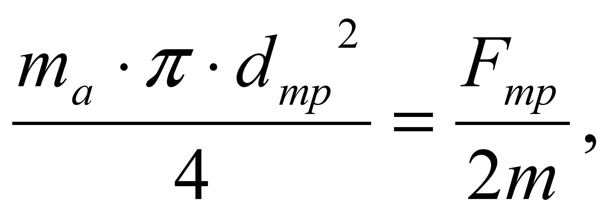
where m a = 0.8 – coefficient taking into account the weakening of the section by thread, according to clause 3.4 of SNiP II – 25 – 80
T= 0.85 – coefficient taking into account the uneven operation of double strands according to clause 3.4 of SNiP II – 25 – 80

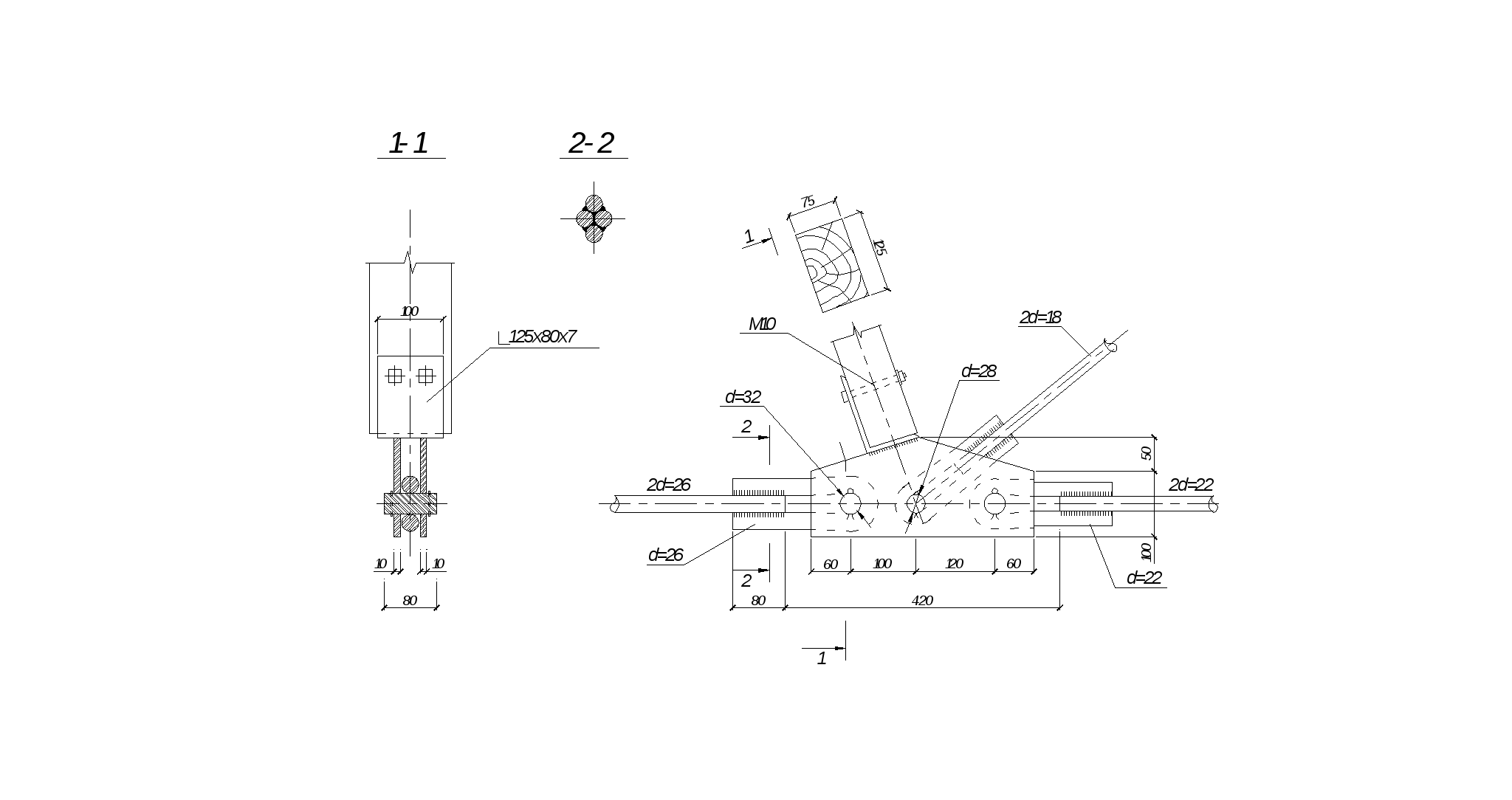
All elements are taken from two rods of the following diameters: lower chord at the supports d= 26 mm; middle element of the lower belt d= 22 mm, brace – d= 18 mm. To reduce the sagging of the lower one, we provide a suspension made of strands d= 10 mm. According to the condition of equal strength, we accept the diameters of the loops for attaching the strands to the intermediate nodes of the lower chord: for the lower chord at the supports d n= 26 mm; for the middle element of the lower chord d n= 22 mm; for brace d n= 18 mm.
The strands of the middle element of the lower chord are located close to each other and welded together along the length every 1 m. In other elements, the strands are brought together closely at a distance of 1 m from the intermediate nodes of the lower chord.
Rack. Design force N 3-11 = 20.4 kN, design post length
l= 1.05m.
According to the assortment, we accept a rack section of 125x75 mm. We check the accepted cross-section:
From the condition of the sub-beam being crushed across the fibers under the end of the post:
Where l cm = 7.5 cm – length of the crushing area along the wood fibers:
For stability in the plane of the truss:


2.2. Calculation of nodal connections.
Support node. Design forces in nodal elements: N 1-2 = 96.67 kN,N 1-11 = 86.45 kN, R 1 = 40.32 kN, - support reaction from the design load.
The required length of the horizontal support area from the condition of the strapping beam across the fibers at

determined by the formula:

we accept l mountains =12 cm.
To create a horizontal support platform, we use a cushion with a cross-section of 125x260 mm and a length of 500 mm with milling of the horizontal platform up to 150 mm. The cushion cuts into the beam of the upper chord to a depth of 80 m, which ensures the required eccentricity
and a sufficient crushing area of the end 8 cm > h cm = 5.18 cm.
We check the length of the pillow by chipping along its length:
Where  - design resistance of wood to chipping.
The pillow is attached to the beam with two pairs of bolts d = 16mm. The lower chord is connected to the support unit by a traverse welded from channel No. 8 with a wall reinforced with a sheet 4 mm thick and a sheet measuring 8x120 mm. The width of the sheet provides the required height of the crushing area of the end of the upper chord (cushion), equal to h cm = 5.24 cm. The traverse is calculated for bending with a design span equal to the distance between the branches of the lower chord:
l tr= 12.5 + 2.6 = 15.1 cm.
Design moment:
Geometric characteristics of the section:
cross-sectional area:
center of gravity position:
 ;
;
section moment of inertia:
minimum moment of resistance:

Normal voltages:
where R y = 330 MPa is the design resistance of steel to bending at the yield strength.
We check the traverse sheet for bending under pressure from the force in the lower chord:

where 12 cm is the length of the traverse.
Bending moment for a strip of the middle section with a design width b p = 1 cm with a span of 8 cm and clamped ends:

the same for the cantilever section with overhang l To= 2cm:

Required slab thickness:

we accept 8mm.
The truss is fastened to the strapping beam using bolts d = 12 mm on corners 63x5 mm.
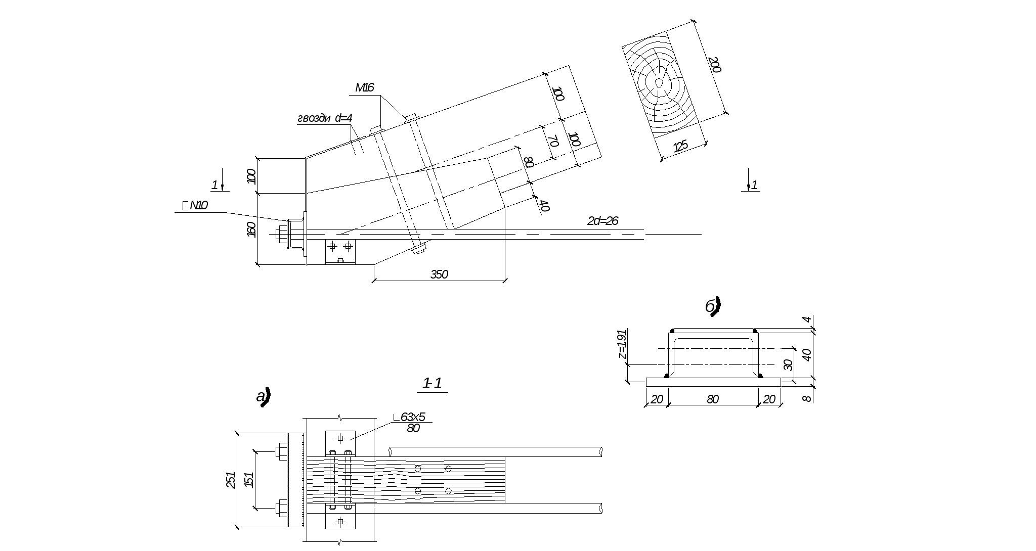
Support unit: a – unit design; b – cross-section of the cross-beam.
Bottom Belt Knot
Design forces in elements: N 1-11 = 86.45 kN, N 10-11 = 54.51 kN, N 3-11 = 20.42 kN, N 5-11 = 32.32 kN. The gussets in the assembly are made of sheet steel  =10mm with holes for turned rollers. The elements of the lower chord and brace are attached to the unit using loops, the diameters of which are calculated above. The design span of the rollers is equal to l V= 2.6 + ? = 3.6 cm. Design moment in the rollers for fastening horizontal ties (at maximum force):
required roller diameter:

We take d in = 32 mm.
We check the accepted roller diameter:
for cutting:
Where  - calculated resistance of rolled products to crushing in cylindrical hinges.
Similarly, we select a roller d = 28 mm for attaching the brace.
The smallest width of the gussets at the point of weakening by the holes:

We accept for constructive reasons:
We accept  = 10 cm >
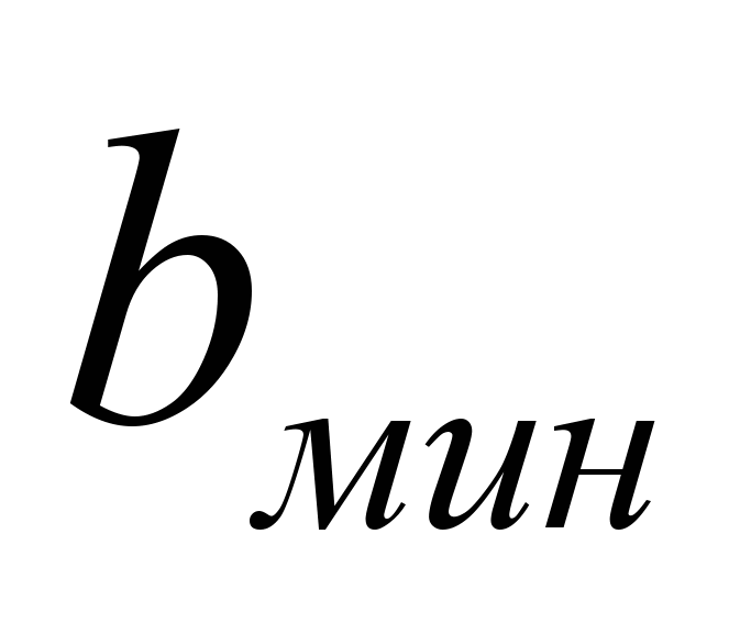
k f= 4 mm for attaching loops to strands of two round rods is determined by formula 120 SNiP II - 23 - 81:
Where 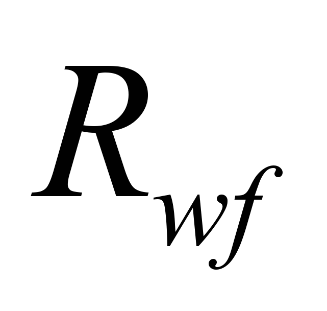 - calculated resistance of the metal of welds of welded joints with fillet welds, taken according to table. 56 SNiP II – 23 – 81;
 - coefficient of weld operating conditions depending on the climatic region according to clause 11.2 of SNiP II - 23 - 81;
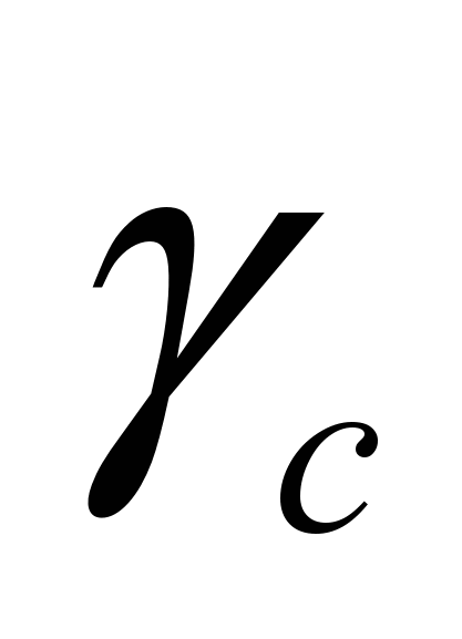 - coefficient of working conditions, taken according to table. 6 SNiP II – 23 – 81
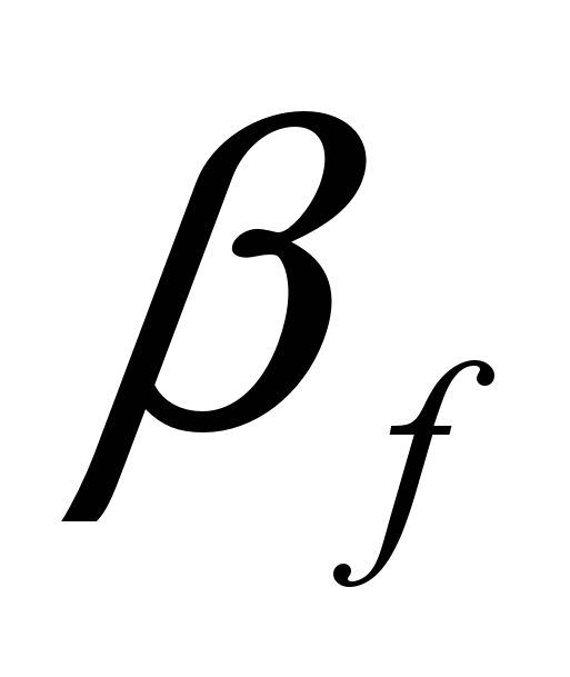 - coefficient depending on the type of welding according to table. 34 SNiP II – 23 – 81
We accept l w= 8 cm.
In this case, only compressive forces arise in the rack; we rest it against a corner 125x80x7 mm, welded to the gussets, and fasten it with two bolts d = 10 mm.
Intermediate knot of the lower belt.
Intermediate knot of the upper belt. The force from one element of the upper chord to another is transmitted by the frontal stop of the ends through the crushing areas, the height of which is equal to
h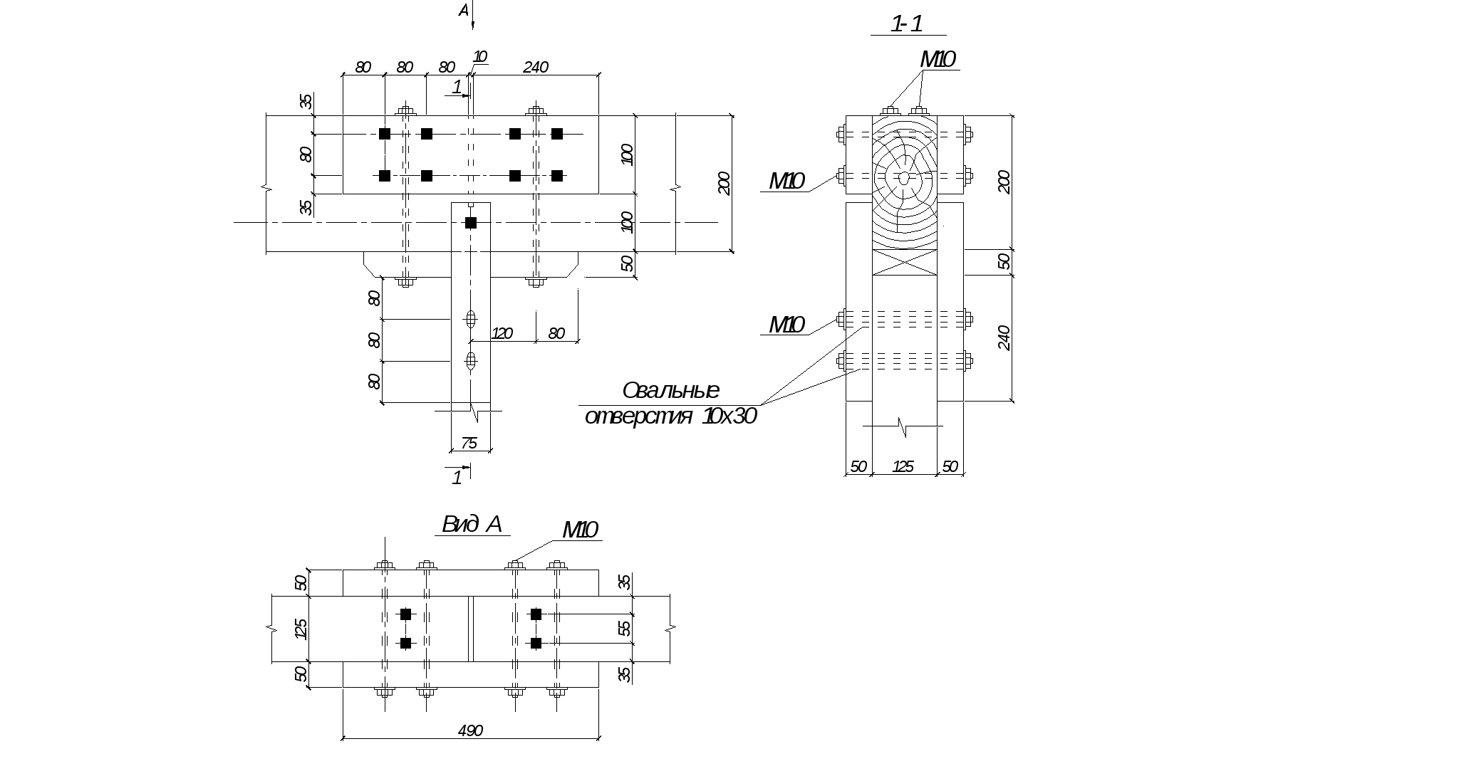 tr =
h– 2e= 2 - 2*9 = 20 - 14 = 6 cm, which exceeds the required. The joint in the assembly is covered with two wooden plates with a cross-section of 50x150 mm and a length of 49 cm on bolts d = 10 mm, which ensure the rigidity of the assembly from the plane.
Intermediate knot of the upper belt.
The force from the rack is transmitted to the upper belt through the end by the stop. Overlays made of bars with a cross-section of 50x75 mm and a length of 390 mm and bolts with a diameter of d = 10 mm are accepted structurally.
Ridge knot. The calculated forces in the node elements are equal to: N 4-5 = 84.91 kN, N 5-11 = 32.32 kN. The force from one element to another is transmitted by the frontal stop at an angle?. The area of the frontal support is equal to
Design bearing resistance when the force is directed at an angle? = 20.48 0 and the direction of the wood fibers will be:
The collapse test is carried out using the formula:
To ensure the rigidity of the unit, paired pads with a cross section of 50x100 mm are structurally fastened from the plane of the truss above the design axis using 6 bolts with a diameter of 10 mm. Below the design axis, using two bolts, we fasten metal plates 8 mm thick on both sides, to which we weld braces and a fastening element for a vertical suspension made of a round rod with a diameter of 10 mm.
We accept bolts with a diameter of 16 mm for fastening metal plates. Resultant tensile force:
Where A 1
= arctg 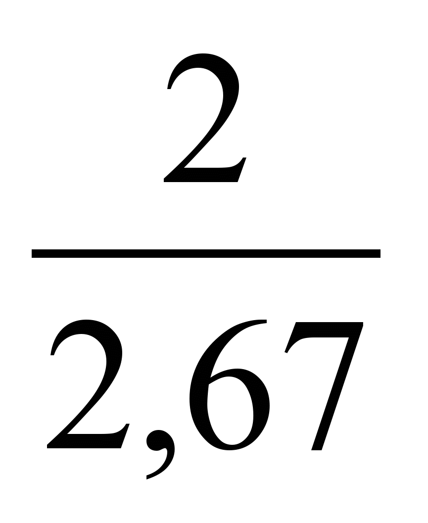 = 36,83 0 .
The bolts transmit force to the plates at an angle of 90 0 – A= 69.52 0, therefore, TO A= 0.668 according to table. 19 SNiP II-25-80. The design capacity of bolted connections is determined from the conditions:
crumpling of the wood of the middle element
bolt bending
Required number of bolts:

We accept 6 bolts with a diameter of 16 mm.
Minimum length welds at the seam leg k f= 4mm for attaching brace elements to a metal plate is determined by the formula:
We accept the length of the seam: l seam= 6 cm.
3. Glued stand of a single-span frame.
Design a laminated plank rack for an industrial building rigidly connected to the foundation.The span of the building is l=12 m, the height of the columns is H=4.5 m. The load-bearing structures of the covering are gable beams. The pitch of the supporting structure is B = 6 m. The enclosing structures of the covering and wall panels are 6 m. The stability of structures is ensured by the installation of pitched and vertical connections in the covering and vertical longitudinal connections between the posts.
Static calculation.
Permanent design loads:
From the weight of the coating q p = 0.446 kPa
From the weight of the beam q b = 0.059 kPa
From the weight of the wall fence q st = 0.446 kPa
Live loads:
Snow standard Sn = 0.7 kPa
Snow calculated Sp = 1.12 kPa

Where – w 0 =0.38 kPa – standard pressure value for wind region III,
K – coefficient taking into account changes in wind pressure along the height, k = 0.75 up to a height of h=5m.
C e – aerodynamic coefficient: c e1 = +0.8; with e3 = -0.4 according to SNiP 2.01.07-85.
Pressure w m 15 = kPa
Suction w m 25 = kPa
Due to the slight change in wind load along the height, we assume it to be constant over the entire height.
The calculated wind load on the frame from the covering (from the section of the wall above the top of the racks h 0 = 0.5 m) is taken in the form of a concentrated horizontal force applied to the top of the racks.
Constant design pressure on the rack from the overlying structures
We determine the own weight of the rack by specifying the preliminary dimensions of its section; section height h k = (1/15)6 = 0.4 m, We take the cross section of the rack from 12 layers of boards 33 mm thick, then h k = 33 * 12 = 396 mm. The width of the column section is taken equal to b k = 185 mm (after milling the side surfaces of the column glued together from boards 200 mm wide). Own weight of the stand:
Where 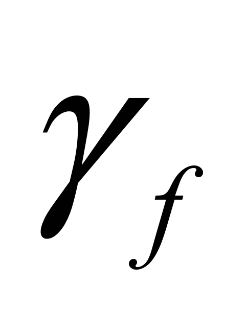 - 1,1;
  = 5 kN/m3 – density of pine wood.
Design load from the wall fence, distributed vertically, taking into account fastening elements (15% of the weight of the wall fence)
Eccentricity of wall load application 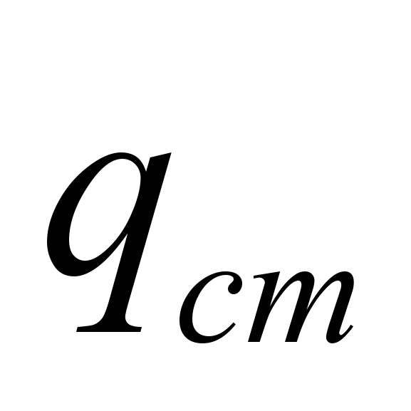 per rack is taken equal to half the sum of the heights of the sections of the rack and the wall:
We determine the forces in the frame struts by taking the following combination of loads: constant, snow, wind. The frame is once a statically indeterminate system; the unknown force is taken to be the longitudinal force X in the crossbar:
Internal forces in the sections of the rack from the top (x = 0.0 m) to the embedment on the support (x = H) are determined by the formulas:
Bending moments in the left and right pillars
Lateral forces:
Normal forces:
Where 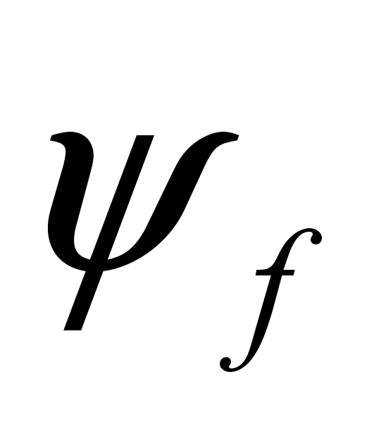 = 0.9 coefficient of combinations introduced for short-term loads while simultaneously taking into account two short-term loads - snow and wind.
Table Internal forces in the frame struts.
| Hm | Mx lion, kNm | Mx pr, kNm | Qх lion, kN | Qx pr, kN | Nx,kN |
| 0 | 0,01 | -0,01 | -0,06 | 1,36 | 41,96 |
| 1 | 0,82 | 1,78 | 1,72 | 2,18 | 42,92 |
| 2 | 3,36 | 4,43 | 3,49 | 3,00 | 43,88 |
| 3 | 7,62 | 7,95 | 5,26 | 3,82 | 44,84 |
| 4 | 13,62 | 12,33 | 7,03 | 4,64 | 45,8 |
| 5 | 21,34 | 17,57 | 8,80 | 5,47 | 46,76 |
Constructive calculation.
In the plane of the frame, the rack acts as a vertical console clamped on a support under conditions of compression and bending. From the plane of the frame, the rack is a rod with fixed hinges at the ends.
The cross section of the rack has dimensions of 185 x 396 mm, then:

In the plane of the frame, the calculation of the rack is carried out as a compressed - bending element. We determine the flexibility of the rack, in the bending plane, assuming that the building does not have rigid end walls.
Where 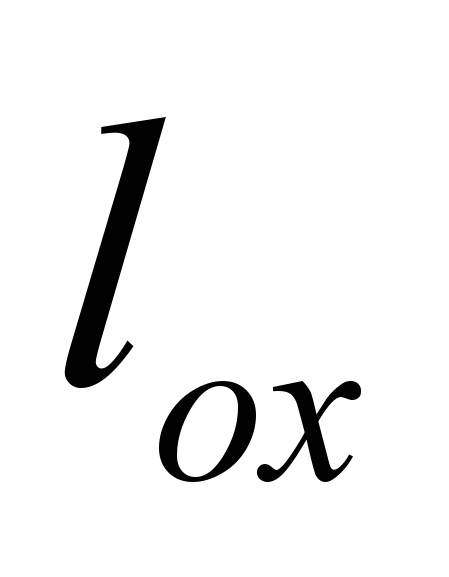 =2.2*N
according to formula (30) SNiP II-25-80
where Rc = 15 MPa for wood (multiply by the operating conditions coefficient m n = 1.2 according to Table 6 of SNiP II-25-80) 2nd grade,  .
.
We calculate the strength of the rack using the formula
From the plane of the frame, we calculate the column as a centrally compressed element. The distance between the nodes of vertical connections is set according to maximum flexibility ![]() .
.
Therefore, it is enough to unfasten the rack along its top, then:
We check the stability of a flat form of deformation using the formula
 Where
Where  =0,42
=0,42
k f – coefficient depending on the shape of the moment diagram.
Consequently, the stability of the rack is ensured.
Calculation of the column base unit.
We determine the required moment of resistance of the channels using the formula:
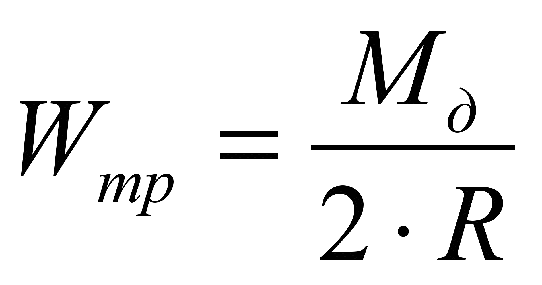
Where R is the design resistance of steel

According to GOST 8240-72, we select channels with 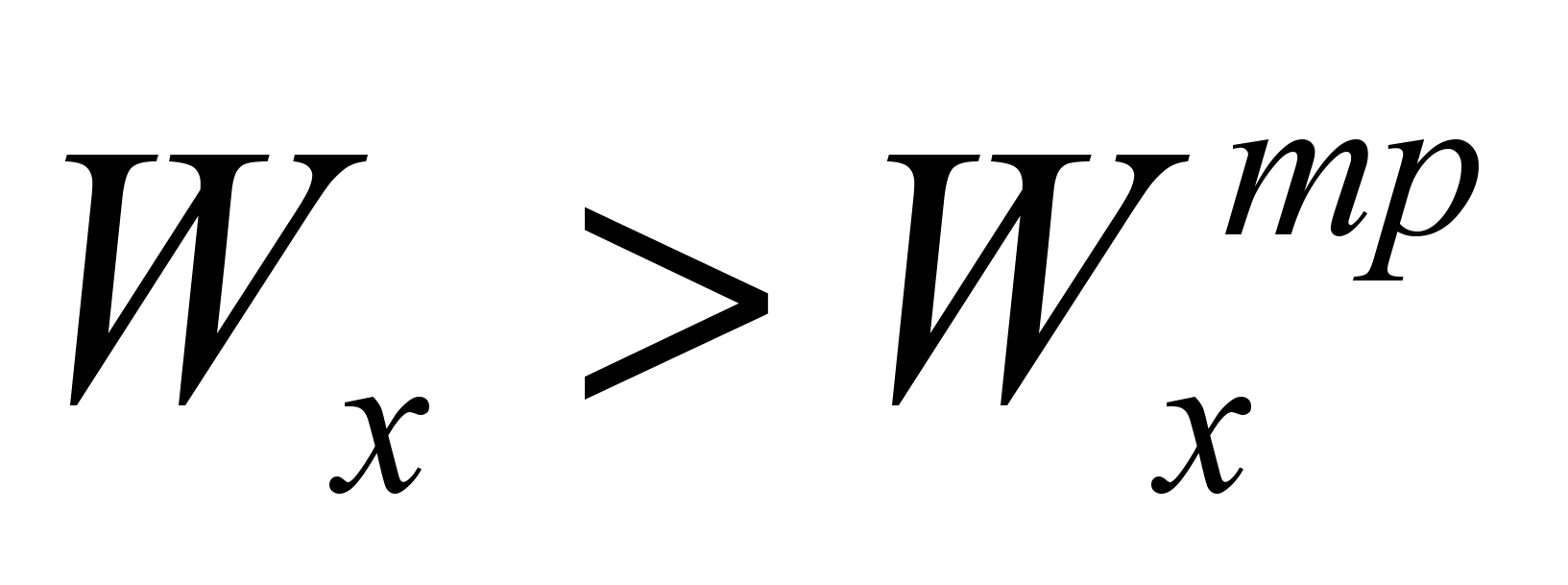 in such a way that the condition is satisfied
 ![]()
Such channels will be No. 18.
We assign the distance between the axes of the strands h 0 from the condition that h 0 be no less than 0.1H and no less than 2h with rounding up by a multiple of 50 mm. We take h 0 =0.8 m.
Where  - design lateral force determined from the expression:
 =
=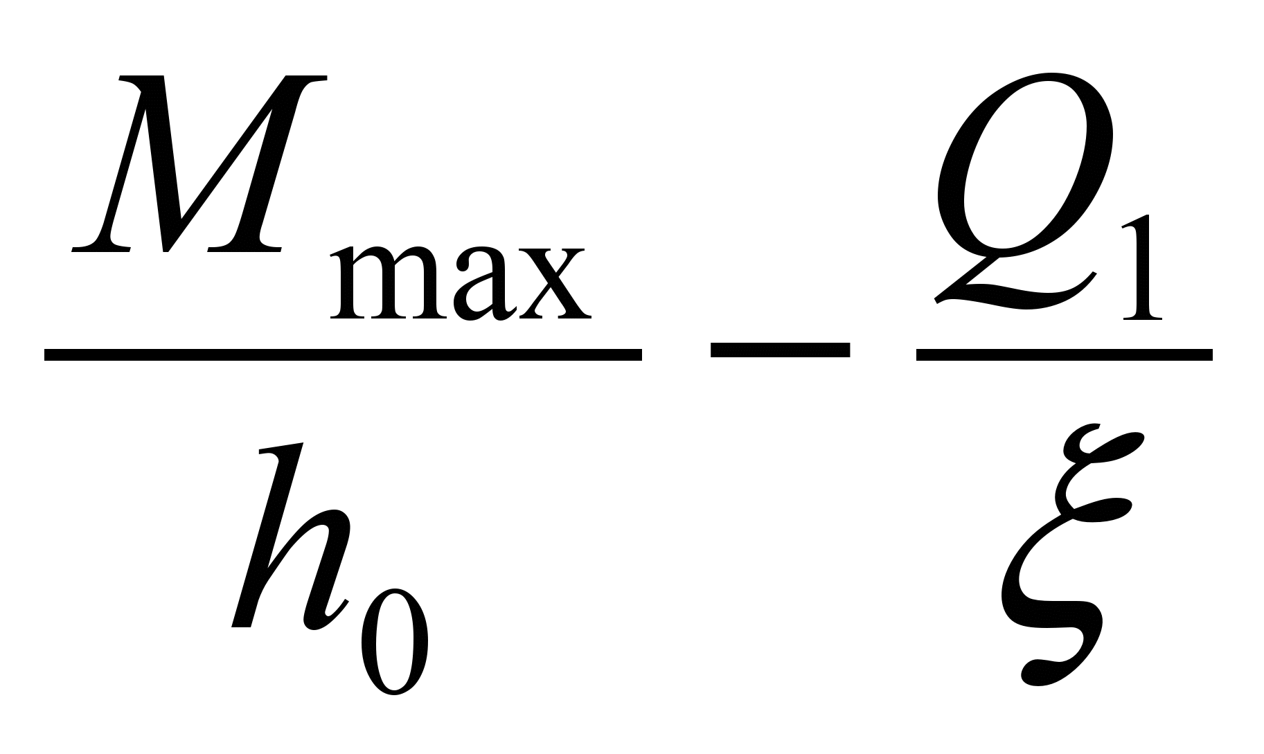 , in which
  -lateral force in the stance at the level of the upper bands. At x = 4.5-0.8 = 3.7 m = 6.5 kN.
=
We determine the force acting in the strands and crushing the wood of the stand under the planks across the fibers

4. Determine the cross-sectional area of one steel strand in a weakened section using the formula 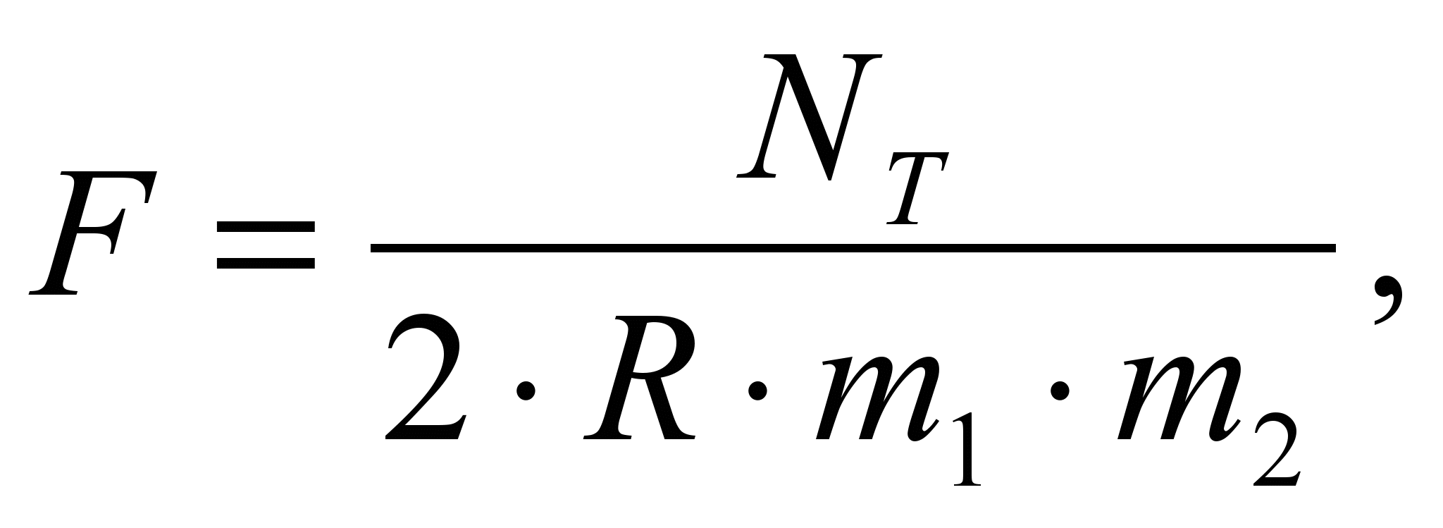
Where m 1 =0.8 is a coefficient that takes into account the influence of cutting;
M 2 =0.85 is a coefficient that takes into account possible uneven distribution of forces in double strands.

From F nt we find the diameter of the strands d br = 12 mm.
We determine the width of the slats from the condition.
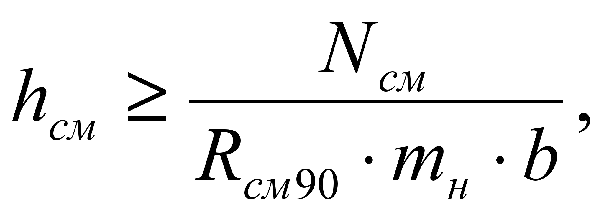
Where 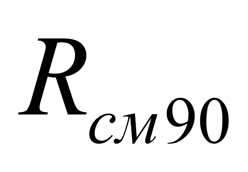 =3 MPa; m n =1.4 according to SNIP II-25-80 table 6.

We take the width of the slats to be 0.06 m.
Determining the thickness of the planks? based on their bending as single-span simply supported beams loaded with a uniformly distributed load q with a design span l pl equal to the distance between the axes of the tie rods
Where  - channel wall thickness,
 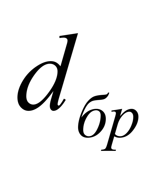 - diameter of strands.
Support reactions 
Load 
Design bending moment
The thickness of the planks is determined by the formula: 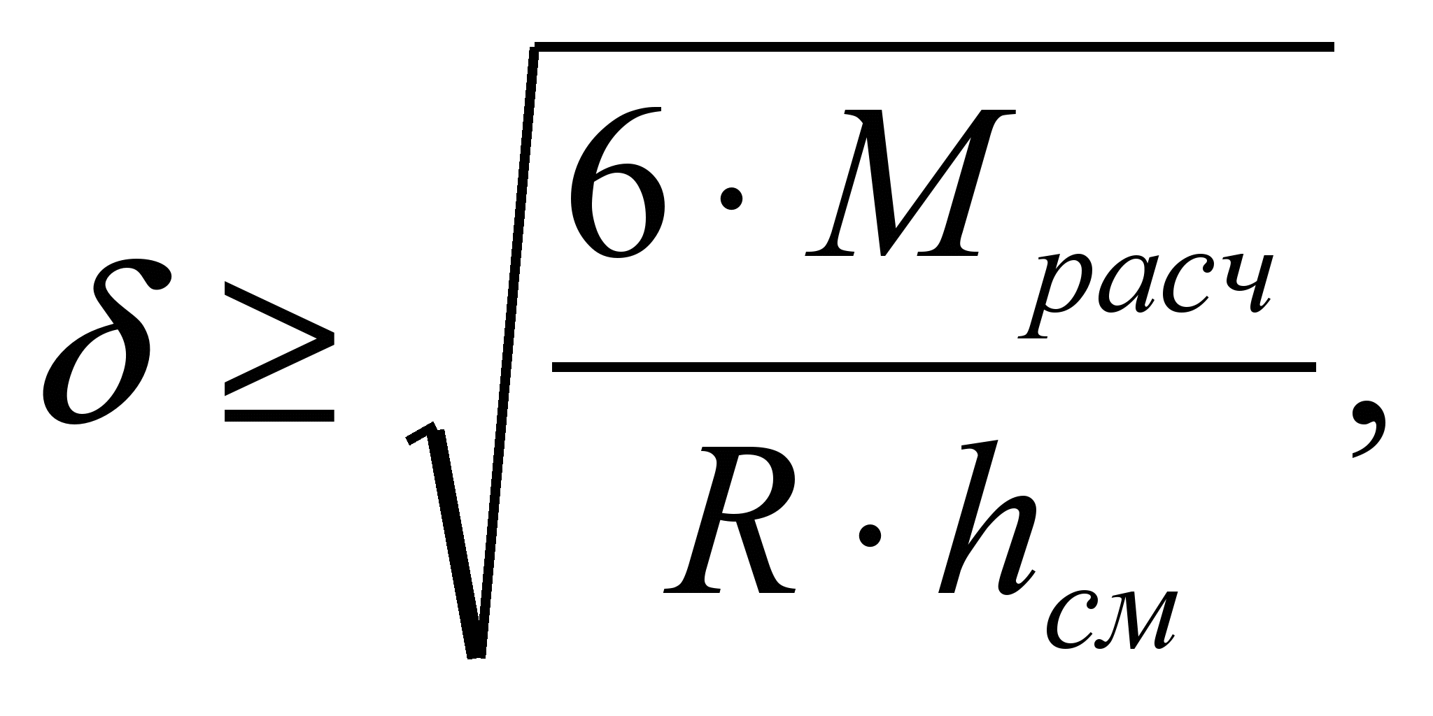

We accept the bar in accordance with the assortment? = 25mm.
If the thickness of the strip turns out to be large (30-40 mm), then instead of sheet strips, strips from a rolled angle should be used.
4. List of references.
SNiP II-23-81 " Steel structures».
SNiP II-25-80 “Wooden structures”.
SNiP 2.01.07-85 “Loads and impacts”.
Buslaev Yu.N., V.P. Ignatiev, D.K. Chakhov: “Design and calculation of wooden trusses.” (textbook), Yakutsk. 2002
Industrial wooden structures. Tutorial for universities / Yu.V. Slitskoukhov, I.M. Guskov, L.K. Ermolenko and others; Ed. Yu.V. Slitskoukhova. – M.: Stroyizdat, 1991 – 256 p.
A manual on the design of wooden structures (to SNiP II-25-80) / TsNIISK im. Kucherenko. – M.: Stroyizdat, 1986-216p.
Structures made of wood and plastics. Example of calculation and design: Proc. manual for universities / Ed. prof. Ivanova V.A. – 3rd ed., revised. and additional – Kyiv: Higher. school. Main publishing house, 1981-392 p.
A.B.Schmidt, Yu.V.Khalturin, L.N.Pantyushina “15 examples of calculation of wooden structures” / Barnaul 1997
Submitting your good work to the knowledge base is easy. Use the form below
Students, graduate students, young scientists who use the knowledge base in their studies and work will be very grateful to you.
Posted on http://www.allbest.ru/
Federal Agency for Education
State educational institution higher professional education
Pyatigorsk State Humanitarian Technological University
Department of Construction
Calculation and explanatory note of course work
Calculation and design of a steel covering truss
1. Initial data
a) span (distance between supports) of the truss - l=27 m;
b) distance (step) between adjacent trusses in the coating - b=12 m;
c) snow area according to load S - VIII;
d) low-slope roof fence design - R = 2.5%;
e) technological requirement for dividing a steel truss into a minimum number of shipping grades of complete factory readiness with installation joints using bolted connections without welding.
The steel roof truss under consideration has a span l = 27 m. The truss pitch (distance between trusses) is b = 12 m. The construction site belongs to the eighth region in terms of snow load. Suspension for lifting and transport and other technological equipment is not provided, therefore the height of the truss in accordance with formula (2) is taken h=l/12=27/12=2.25 m, and the normalized maximum deflection is u = l/250 = 2700/250 = 10.8 cm at l< 36 м.
The truss includes parallel chords, a triangular lattice system with additional posts and consists of three dispatch marks. Two of them are 11.25 m long and have a construction rise that provides the gable roof with a slope of R = 0.025 (2.5%). Between these marks there is a horizontal (H = 0) 4.5-meter insert. The shipping marks are connected to each other using bolted connections on the flanges. The assembly joints communicate with the nodes having kinks in the chords and include connections of additional core elements of the lattice.
The steel covering truss is made of closed bent-welded profiles of rectangular cross-section. Their factory connections are structurally designed in the form of bevelless units and are made by semi-automatic welding in a carbon dioxide environment: the welding material is Sv 08G2S wire with a design metal resistance of fillet welds R wѓ = 200 MPa (2000 kgf/cm 2). As the main construction material low-carbon steel S245 (grade VSt3sp5) with a calculated yield strength R y = 240 MPa (2400 kgf/cm 2) with a rolled thickness t = 4...20 mm and low-alloy steel S345 (grade 09G2S) with R y = 335 MPa ( 3350 kgf/cm 2) at t = 2…10 mm and R y = 315 MPa (3150 kgf/cm 2) at t = 10…20 mm, as well as for stretched flanges - steel S390 (grade 14G2AF) with R y = 380 MPa (3800 kgf/cm 2) at t = 4…50 mm.
The standard value of the load from the self-weight of the steel covering truss is calculated using formulas (5) and (6)
m s = k m l = (0.4…0.8)27 = 10.8…21.6 kg/m 2 ;
m= m m s =(1.03…1.05)(10.8…21.6) = 11.12…22.68 kg/m 2
and in the calculation it is assumed to be 23 kgf/m 2.
Further collection of the design load is given in table. 1.
Table 1. Determination of the design load, kN/m 2 (kgf/m 2)
|
Normative value |
Reliability factor |
Estimated value |
||
|
gravel protection |
||||
|
roll carpet |
||||
|
insulation |
||||
|
vapor barriers |
||||
|
runs |
||||
Having determined the standard and design values of the load acting on the truss, its minimum height should be calculated from the rigidity condition using formula (3):
where y n = (p n /p)R y, since the rigidity condition is checked under the action of a standard load; p n = 4.71 kN/m 2 - standard load; p = 6.428 kN/m 2 - design load; R y = 240 MPa and E = 210000 MPa - respectively, the resistance and elastic modulus of steel.
As you can see, h min = 1.836 m =l/14.7< l/12 =2,25м и принятое в расчете значение высоты фермы не нуждается в корректировке.
2. Static calculation of a flat truss
The load acting on the steel roof truss is collected from a load strip with a width of b = 6 m and is:
q n = p n b= 4.71*12 = 56.52 kN/m - standard linear;
q = pb = 6.43*12 = 77.16 kN/m - calculated linear length.
Covering structures include purlins that transfer the linear load to the truss through its upper nodes (Fig. 1, a):
F n = q n d = 56.52*2.25 = 127.17 kN - standard nodal;
F = qd = 77.16*2.25 = 173.61 kN - design node.
Rice. 1. Schemes for static calculation of a truss: a - load on the truss; b - beam analogue of the truss and diagrams of bending moments of transverse forces.
For the static calculation of a flat truss, you can use its beam analogue (Fig. 1, b) with support reactions
V 1 = V 1 3 = F i /2 = ql/2 = 77.16*27/2 = 1041.66 kN.
Bending moments due to loads are:
M 1 = M 1 3 = 0;
M 2 = M 12 = (V 1 - F/2)*d = (1041.66-173.61/2) *2.25= 2148.43 kN*m;
M 3 = M 11 = (V 1 - F/2)*2d -Fd =(1041.6-86.8)4.5-173.6*2.25 = 3906.3 kN*m
M 4 = M 10 = (V 1 - F/2)*3d -F*2d - Fd=(1041.66-86.8)6.75-173.6*4.5-173.6*2, 25= 5273.5 kN*m
M 5 = M 9 =954.86 *9-1171.8-781.2-390.6 = 6250.14 kN*m
M 6 = M 8 = (1041.6-86.8)11.25-1562.4-1171.8-781.2-390.6 =6836.2 kN*m
M 7 = M max = (V 1 - F/2)*6d - Fd(5+4+3+2+1) = (1041.66-86.8)13.5-1953-1562.4-1171 ,8-781.2-390.6=7031.6 kN*m;
The bending moment M 7 acts in the section of the beam analogue of the truss in the middle of the span l and is the largest. In the presence of 13 nodal loads F and F/2, it is advisable to compare it with a similar moment from a distributed (linear) load:
M max = ql 2 /8 = 77.16*24 2 /8 = 7031.2 kN*m.
As you can see, the absolute values of the compared moments coincide here.
Transverse forces from the action of nodal loads are:
Q 1-2 = - Q 12-13 = V 1 - F/2 = 1041.66-86.8 = 954.86 kN;
Q 2-3 = - Q 11-12 = V 1 - F/2-F=1041.66-173.6-86.8=781.26 kN;
Q 3-4 = - Q 10-11 = V 1 - F/2-2F=607.66 kN;
Q 4-5 = - Q 9-10 = V 1 - F/2-3F=434.06 kN;
Q 5-6 = - Q 8-9 = V 1 - F/2-4F=260.46 kN;
Q 6-7 = - Q 7-8 = V 1 - F/2-5F= 86.86 kN;
Let's calculate the elongation of the truss rod elements.
l 7-16 =l 7-17 =hv2=2250v2=3182 mm
3230-3182=48 mm.
3182-3135=47mm.
2,083…2,128%.
The values of longitudinal forces in the belt elements are calculated using the formula:
N 1-2 = N 2-3 = N 11-12 = N 12-13 = - M 2 /h = - 2418.84/2.25 = -954.86 kN;
N 3-4 = N 4-5 = N 9-10 = N 10-11 = - M 4 /h = - 5273.5/2.25 = -2343.7 kN;
N 5-6 = N 6-7 = N 7-8 = N 8-9 = - M 6 /h = - 6846.175/2.25 = -3038.3 kN;
N 14 -1 5 = N 18-19 = M 3 /h = 3906.27/2.25 = 1736.12 kN;
N 15-16 = N 17-18 = M 5 /h = 6250.14/2.25 = 2777.84 kN;
N 16-17 = M 7 /h = 7031/2.25 = 3124.8 kN,
where the minus sign denotes compression forces (upper belt), and the plus sign indicates tensile forces (lower belt).
Longitudinal forces in the diagonal elements of the lattice are found using the formula
N р = ± Q/cosв;
N 1-14 = Q 1-2 /cosв = 47.7/cos45 0 =954.86/0.7071 = 1350.39 kN;
N 3-1 4 = Q 2-3 /cosв = - 781.26/0.7071 = -1104.88 kN;
N 3-15 = Q 3-4 /cosв = 607.66/0.7071 = 859.37 kN;
N 5-15 = Q 4-5 /cosв = - 434.06/0.7071 = - 613.86 kN;
N 5-16 = Q 5-6 /cosв = 260.46/0.7071 = 368.35 kN;
N 7-16 = Q 6-7 /cosв = - 86.86/0.7071 = - 122.84 kN;
where cosв = h/d s = 2.25/3.182 = 0.7071
The rod elements of the lattice posts experience compression, the magnitude of which is determined by the value of the nodal loads:
N 2-14 = N 4-15 = N 10-18 = N 12-19 = - F = - 173.6 kN.
The forces in the nodes from the fracture of the lower belt are perceived by additional lattice rods, each of which works in tension, calculated by formula (16), but without the factor 2:
N 6-16 = N 8-17 = -F+N 16-17 sinb = -173.6+3038.3*0.025 = -97.64 kN,
where with a slope R = 0.025 (2.5%) is the angle of inclination to the horizon b? sinb? tgb = I.
The results of the static calculation of the truss are given:
Rice. 2. Diagram of the truss with the results of its static calculation (forces are given in kN, dimensions in mm, the plus sign corresponds to tension).
3. Unification and calculation of rods
The steel covering truss is assembled from symmetrical starting marks 11.25 m long and a 4.5-meter insert between them. Therefore, it is rational to select the sections of their belt elements according to maximum forces and unify them within the entire span. The height of these sections, as well as the rod elements of the lattice, must be limited to 1/15...1/10 of the length in order not to take into account additional bending moments from the rigidity of the welded units of the truss. In addition, in this case preference is given constructive solution trusses using closed profiles and their connections without nodal gussets.
It is advisable to begin the selection of sections with stretched rod elements. Taking C345 steel with a calculated yield strength R y = 335 MPa (3350 kgf/cm 2) with a rolled thickness t = 2...10 mm as a structural material for the lower belt, from formula (18) we can write:
And required =N/ (g c R y) = 312500/(1·3350) = 93.28 cm 2,
where N = 3124.8 kN = 312500 kgf - the greatest tensile force in the belt.
According to the range of square profiles (Appendix 1), can a core element be accepted? 3008.5 mm with a calculated cross-sectional area A = 96.63 cm 2, radii of gyration R x = R y = 11.82 cm and strength testing
N/(g c R y A) = 312500/(1 3350 96.63) = 0.965< 1.
The compressed rods of the upper chord are loaded no less than the lower one. If we take steel C345 for them, then from the stability conditions according to formula (19) of the methodological instructions it will follow that
And the orientation. = N/ (c g c R y) = 303830/(0.8 1 3350) = 113.37 cm 2,
where N = 303.83 tf (303830 kgf) - the greatest compression force in the belt; q = 0.8 - buckling coefficient for the first approximation.
To increase the degree of unification when selecting the cross-section of the upper chord, it is advisable to take into account the transverse size of the already adopted lower chord. Therefore, from the assortment of rectangular profiles (Appendix 2), a rod element of 4003007.0 mm with A = 94.36 cm 2 and radii of gyration R x = 15.36 cm is selected; I y = 12.34 cm.
With appropriate fastening of sheets of profiled flooring to each other and to the covering purlins, a hard disk is formed, which prevents the movement of the upper chord nodes in the direction from the plane of the truss. Therefore, the design length of the upper chord is l x =l y = 225 cm, and its flexibility l x =225/15.36 = 14.648 - in the plane of the truss; l y = 225/12.34 = 18.23 - from the plane of the truss. The last parameter is crucial in determining the buckling coefficient, calculated in this case using formula (20) of the guidelines:
q = 1 - 0.066 = 1 - 0.066 0.728 = 0.959
where = l = 18.23 = 0.728< 2,5 - условная гибкость.
Checking the stability of the upper chord is as follows:
N/ (c g c R y A) = 303830/(0.959*1*3350*113.63) = 1.002?1< 1.
To prevent the belts from pushing through, it is recommended that the transverse size of the lattice rods be at least 0.6 of the width of the belt element, that is, 0.6*300=180 mm. Less durable but more affordable steel C 245 with R y = 240 MPa (2400 kgf/cm 2) at t = 4...20 mm is used as the structural material of the lattice rod elements.
Of all the braces of the lattice, the most loaded is the support one, which is stretched with a force of N = 1350.39 kN (135039 kgf, brace 1-14) and for which, according to the strength condition according to formula (18) of the guidelines
And required = N/ (g c R y) = 135039 / (1 * 2400) = 56.27 cm 2.
According to the assortment of square profiles (Appendix 1, a rod element is selected? 1809 mm with A = 58.78 cm 2 and i x = 6.89 cm. The estimated length of the support brace in the plane and from the plane of the truss is l x = 273 cm, flexibility l x = 313 .5/6.89= 45.5; and the strength test shows that
N/ (g c R y A) = 135039/ (1*2400*58.78) = 0.957< 1,03.
Brace 3-14 is the most loaded of the compressed lattice bars. From the stability condition according to formula (19) of the methodological instructions it follows that
And the orientation. = N/ (tsg c R y) = 110488/(0.8*1*2400) =57.546 cm 2,
According to the assortment of square profiles (Appendix 1 of the guidelines) is the core element selected? 2007 mm with A = 52.36 cm 2 and i x =i y = 7.81 cm. Design length of the support brace in the plane and from the plane of the truss l x = l y = 323 cm, flexibility l x = 323/7.81 = 41 .35; and the strength test shows that
N/ (tsg c R y A) = 110488/ (0.891*1*2400*52.36) = 0.986< 1.
where q = 1 - 0.066 = 1-0.066*1.398 = 0.891 - buckling coefficient, calculated using formula (20) of the guidelines;
41,35 = 1,398 < 2,5 - условная гибкость;
For the internal brace 3-15, which experiences tension with a force N = 859.37 kN (37247 kgf), we determine the strength conditions using formula (18) of the guidelines:
And required = N/ (g c R y) = 85937/(1·2400) = 35.807 cm 2.
Is the core element selected according to the range of square profiles? 1805.5 mm with A = 37.61 cm 2 and i x = 7.09 cm. Strength testing shows
N/ (g c R y A) = 85937/ (1*2400*37.61) = 0.95< 1.
The internal brace 5-15 experiences compression with a force N = -613.86 kN (61386 kgf) and for which, from the strength condition according to formula (18) of the guidelines
And the orientation. = N/ (c g c R y) = 61386/(0.8*1*2400) = 31.97 cm 2.
According to the assortment, do we accept a rectangular profile? 1201806 mm with A = 33.63 cm 2 and i x = 4.87 cm. The estimated length of the support brace in the plane and from the plane of the truss l x = l y = 323.0 cm; and the strength test shows that
N/ (tsg c R y A) = 61386/ (0.778*1*2400*18.34) = 0.98< 1.
where q = 1 - 0.066 = 1-0.066*2.24 = 0.778 - buckling coefficient, calculated using formula (20) of the guidelines;
66,32 = 2,24 < 2,5 - условная гибкость;
l = 292.9/4.87 = 66.32 - calculated flexibility;
For the internal brace 5-16, which experiences tension with a force N = 368.35 kN (36835 kgf), we determine the strength conditions using formula (18) of the guidelines:
And required = N/ (g c R y) = 36835/(1*2400) = 15.348 cm 2.
Is the core element selected according to the range of rectangular profiles (Appendix 2) of the guidelines? 60180 4 mm with A = 18.15 cm 2 and i x = 6.11 i y = 2.56 cm. Strength testing shows that
N/ (g c R y A) = 36835/ (1*2400*18.15) = 0.846< 1.
The internal brace 7-16 experiences compression with a force N = -122.84 kN (12284 kgf) and for which, from the strength condition according to formula (18) of the guidelines
And the orientation. = N/ (c g c R y) = 12284/(0.8*1*2400) = 6.4 cm 2.
According to the assortment, do we accept a rectangular profile? 60180 4 mm with A = 18.15 cm 2. The estimated length of the brace in the plane and from the plane of the truss l x = 52.08 l y = 124.3 cm; and the strength test shows that
N/ (tsg c R y A) = 12284/ (0.432*1*2400*18.15) = 0.653< 1.
The lattice racks are subjected to compression with a force N = -17.361 tf (17361 kgf, racks 2-14, 4-15, 6-16) and for which, from the strength condition according to formula (19)
And the orientation. = N/ (tsg c R y) = 17361/(0.8*1*2400) = 9.042 cm 2.
According to the assortment, do we accept a rectangular profile? 18060 4 mm with A = 18.15 cm 2 and i x = 6.11 cm 2. The estimated length of the brace in the plane and from the plane of the truss is l x = l y = 225 cm; and the strength test shows that
N/ (tsg c R y A) = 17361/ (0.91*1*2400*18.15) = 0.438< 1.
where c = 1-0.066*1.25v1.25 = 0.91 - buckling coefficient, calculated according to formula (20) of the guidelines;
36,825 = 1,25 < 2,5 - условная гибкость;
l = 225/6.11 = 36.825 - design flexibility
The main results of the calculation of the truss rods are presented in tabular form (Table 2).
Table 2. Results of selecting the cross-section of the rods.
|
Results of selection of rod cross-sections |
|||||||||||||||||
|
Section, mm |
Steel grade |
R y kgf/cm 2 (g c =1) |
|||||||||||||||
All lattice rods directly welded to the upper and lower chords of the truss have transverse dimensions exceeding 0.6 times the width of the chord elements. Additional lattice rods at the bend nodes of the belts are connected to the latter through assembly joints on bolts and flanges. Rods are the main elements of lattice structures such as roof trusses. Their mass mainly affects the basic technical and economic characteristics of a particular design. The mass of the rod elements of the truss under consideration is given in table. 5, where linear dimensions are indicated in axes without taking into account structural eccentricities at nodes.
After finding the total mass of the rod elements, you can calculate their reduced mass:
m s = 4990.6/(27*12) = 15.4 kg/m2,
where the value in the denominator determines the load area of the covering truss. It is interesting to compare the resulting parameter with the values used when collecting loads
m s = 10.8...21.6 kg/m 2.
Table 3. Mass of rod elements
|
Section, mm |
Quantity, pcs. |
Weight, kg |
Note |
||||
It is obvious that with increasing load (for example, from the weight of the snow cover), the reduced mass of the rod elements will increase, approaching the upper value. The existing difference in the m s values of the calculated truss can be included in the overall safety factor of the structure being developed and used in the process of further operation, as well as possible reconstruction.
Rice. 3. Layout diagrams of rods in the form of sending marks for the coating truss: F-11.25 and F-4.5 - marking of sending truss elements
Unified and calculated rods must be arranged with each other in the form of shipping marks into which the covering truss is divided. To construct the truss elements, a two-scale image is used. When designing chamferless joints of rectangular and square closed profiles, nodal eccentricities are used, the value of which in this case should not exceed:
400/4 = 100 mm - in the upper zone;
300/4 = 75 mm - in the lower belt.
In such units, the rod elements are adjusted to each other with the obligatory presence of gaps between the nearest welds, which are at least 10...20 mm in clearance. The mass of deposited metal in welds made using factory technologies, as a rule, does not exceed 1...1.5% of the mass of the elements being welded.
4. Design and calculation of installation joints
The installation connections of the steel covering truss must be designed taking into account their location at the fracture points of the upper and lower chords. To ensure the required slope (R = 0.025%), the core elements of the chords of 11.25-meter truss starting marks (F-11.25) are welded to the flanges only after a corresponding oblique cut of their ends. Similar waist elements of a 4.5-meter insert (dispatch grade F-4.5), which has a zero slope (I = 0), are distinguished by the straight cut of their ends. In addition, in the joints between the flanges assembled during installation for attaching additional truss lattice rods, flat gaskets made of rolled sheet metal are placed, factory welded to the rod elements of the closed profile.
The mounting joints of the lower chord of the truss perceive the longitudinal force of the chord element F np = N 16-17 = 3124.8 kN and the local transverse force Q loc = N 6-16 = N 8 -17 = -122.84 kN (Fig. 4.) . Such a load in flange connections without prestressing bolts (type B) causes simultaneous tension and shear action in the latter, forcing them to work under conditions of a complex stress-strain state. More preferred flange connections with pre-tensioned bolts (type A), the magnitude of which is such that the longitudinal load cannot release the tightened flanges, and the transverse load cannot overcome the friction between them. The magnitude of the longitudinal force F, which tightens the flanges in this way, is
F = F np + F loc = F np + Q loc /m = 3124.8+122.84/0.25 = 3616.16 kN
where F loc = Q loc /m is the contact force required, according to formula (40), to absorb the lateral load by friction; m = 0.25 - friction coefficient of joined surfaces without processing.
Rice. 4. Diagram of the installation joint of the lower chord of the truss.
To select the cross-section of bolts for design reasons, their total number n in = 8 and strength class 10.9 can be taken. Then from the strength condition (30) taking into account expression (31) we can write:
A bn,req. = F/ (0.9n b R bt) = 361616 (0.9 8 5000) = 10.045 cm 2,
where R bt = 500 MPa = 5000 kgf/cm 2 - calculated tensile strength (Table 7 guidelines).
From the assortment (Table 8 of the guidelines), select an M42 bolt of class 10.9 with a calculated net cross-sectional area A bn = 11.2 cm 2, the strength test of which is as follows:
F/ (0.9n b N bt) = 361616/ (0.9*8*56000) = 0.9<1,
where N bt = R bt A bn = 5000 11.2 = 56000 kgf = 560 kN - the design force, according to formula (31), perceived by one tensile bolt, with which it is pre-tensioned so that the flange connection works according to type A.
The calculated bolted connection M42 must be placed moment-free (symmetrically) relative to the center of gravity of the section of the belt element, as close as possible to it and taking into account the minimum permissible distances from the profile and stiffener to the bolt axis b b = 85 mm and from the bolt axis to the edge of the flange c b = 65 mm (Table 6 guidelines). In this case, each of the 8 bolts must be equidistant from the profile and from the stiffener.
Under load, the flange bends. The values of bending moments are calculated using the formulas (36 guidelines):
M 1 = 0.9N bt l 1 b b (l 1 + c b)/(3l 1 2 - c b 2) = 0.9*56000*15*8.5*(15 + 6.5) / (3*15 2 - -6.5 2)=218347 kgf cm;
M 2 = 0.9N bt b in 2 (3l 1 - b in)/(3l 1 2 - c b 2) = 0.9*56000*8.5 2 (3*15-8.5)/(3* 15 2 - 6.5 2) = 210053 kgf cm,
where l 1 = b in + c in = 8.5 + 6.5 = 15 cm.
From the condition of the flange bending strength (35) for its thickness t – l, taking into account the moment of resistance of the section during the development of inelastic deformations according to the formula (37 guidelines), we can write:
t ѓ l ,req. = = = 3.27 cm,
where M max is the largest bending moment, M max = M 1 = 218347 kgf*cm;
g c - coefficient of working conditions, g c = 1; R y,ѓ l - design resistance of the flange steel according to the elastic limit, R y,ѓl = 380 MPa = 3800 kgf/cm 2 (steel C 390); b 1 - bolt pitch, b 1 = 21.5 cm.
M42 - t ѓl = 40 mm
the last value is accepted. Then the moment of resistance of the section during the development of inelastic deformations is
W ѓ l = b 1 t ѓ l 2 /4 =21.5*4.5 2 /4 = 86 cm 3,
and the bending strength test has the form
M/(W ѓl g s R y, ѓl) = 218347/(86*1*3800) = 0.668< 1.
Without the development of inelastic deformations
W ѓl = b 1 t ѓl 2 /6 = 21.5 * 4.5 2 /6 = 57.33 cm 3
M/(W ѓ l g s R y, ѓ l) = 218347/(57.33*1*3800)=1.002?1
The calculated flange of the stretched joints is welded to the waist element (? 300-3008.5 mm) using one-sided fillet welds. To ensure the required length of such seams, stiffeners are used with a length of 1.5 sides of the profile (but not less than 200 mm) and a thickness of no more than 1.2 times the thickness of the profile, that is, 1.5 * 300 = 450 mm and 1.2 * 8.5 = 10.2?10 mm.
Welds between flanges and waist elements with stiffeners must be checked by strength calculation using formulas (41) - (43) of the guidelines:
For weld metal
F/ (in – k – l w R wѓ g wѓ g c) = 312480/(0.7*1*277.7*2000*1*1) = 0.8< 1;
Metal fusion boundaries with belt element
F/ (in z k ѓ l w R wz g wz g c) =312480 /(1*1*277.7 *1650*1*1) = 0.682< 1;
Along the metal fusion boundaries with the flange in the direction of the thickness of the rolled product
F/ (in z k ѓ l w R th g wz g c) = 312480/(1*1*277.7*1900*1*1) = 0.59< 1,
where F is the load on the welds, F = F np = 312.48 tf = 312480 kgf;
k ѓ - leg of fillet welds, k ѓ = 9 mm? 1.2t min = 1.2*8.5 =10.2 is taken equal to 10 mm; l w is the estimated length of the seam, taken to be 1 cm less than its full length, l w = (30 - 1)4 + (15/0.7071 - 1)8 = 277.7 cm; in ѓ = 0.7; R wѓ = 2000 kgf/cm 2, g wѓ = 1 - semi-automatic welding in a carbon dioxide environment with Sv08G2S wire; in z = 1, g wz = 1, R wz = 165 MPa = 1650 kgf/cm 2 - for steel C 245 stiffeners (Table 3 of guidelines); R th = 0.5 R y = 0.5 3800 = 1900 kgf/cm 2 - for steel C 390 flange.
Here, in the second check, a stiffener made of a less durable material (C 245 steel) than the belt profile (C 345 steel) is taken as a belt element. In addition, here it is necessary to check the strength of the double-sided fillet welds connecting the 4 ribs and the profile:
on weld metal
F/ (in – k – l w R wѓ g wѓ g c) = 312480/(0.7*1*352*2000*1*1) = 0.63< 1;
metal fusion boundaries
F/ (in z k ѓ l w R wz g wz g c) = 312480/(1*1*352*1650*1*1) = 0.54< 1,
where l w = (45 - 1)8 = 352 cm.
To increase the degree of unification, it is advisable to accept bolted connections designed in the tension joints of the lower chord in the compressed joints of the upper chord, where the bolts can be tightened without prestressing them.
Compressed flanges are usually 1.5…2 times thinner than stretched ones (t – l = 45/(2…1.5) = 22.5…30 mm). Taking t ѓ l = 24 mm and b ѓ l = 600 mm - respectively, the thickness and width of the flange required in the supporting unit of the truss is checked by calculation from the condition of bearing strength according to the formula (44 guidelines):
V/ (b – l t – l R p) = 104166/(60*2.4*3600) = 0.2< 1,
where V is the support reaction of the farm, V = 104.166 tf = 104166 kgf; R p - calculated resistance of steel to end surface collapse, for steel C 245 R p = 360 = MPa = 3600 kgf/cm 2 (Table 3 of guidelines).
Fig.5. Diagram of the truss support unit.
The height of the support flange is selected in such a way that, for clear support, it protrudes at least 10...20 mm below the weld connecting it to the belt profile. For a better fit, the bottom end of the support flange must be milled.
In the mounting joints of the upper chord (Fig. 6), the flanges have the same dimensions as in the support units of the truss. The strength of such a flange connection in accordance with the formula (40 guidelines) must be checked by calculating the action of local transverse force, as in the installation joints of the lower chord, amounting to Q loc = 97.6 kN:
Q loc /(mF VP) = 97.6/(0.25*3038.3) = 0.13< 1,
where m = 0.25 is the coefficient of friction of the surfaces being connected without processing them; F VP = N 7-8 = N 8-9 = 3038.3 kN - longitudinal force of the belt element.
Rice. 6. Diagram of the installation joint of the upper chord of the truss.
After designing and calculating the installation joints, you can begin to develop drawings of shipping marks, specifications and a list of shipping elements of the truss. From this statement it follows that the total mass of the truss is 2416.28 kg and, calculated per 1 m 2 of horizontal projection of the coating, is
m = 5796.7/(27*12) = 17.9 kg/m2.
Then, using formula (5), you can calculate the construction mass coefficient
m = m/m s = 17.9/15.4 = 1.16
where m s = 15.4 kg/m 2 is the reduced mass of the rod elements.
5. Calculation of the truss for deformability
To determine the deflection of the truss, it is necessary to calculate the moment of inertia of its cross section in the middle of the span (Fig. 7):
Y c = (94.36*235+96.63*10)/(94.36+96.63) = 121.16 cm;
U np = 121.16-10 = 111.16 cm;
At VP = 225-111.16 = 113.84 cm;
I x = 22261.56+94.36*113.84 2 + 13497.83+96.63*111.16 2 =2452635.11 cm 4.
Rice. 7. Diagram of the cross section of the truss.
The cross-section of the upper and lower chords, as well as the calculated moment of inertia, is constant over the entire span of the truss. Therefore, the influence coefficient of the change in the moment of inertia of the truss section along the span length k I = 1. Then the expression (47 guidelines) for the beam deflection ѓ B can be rewritten as follows:
ѓ B = k I (F I a I) = a I (3l 2 - 4a I 2),
where F I - nodal standard load, F I = F n =12.717 tf =12717 kgf; a I - the distance from the support to the point of application of force F I; in this case, the nodal normative loads Fn are applied at points 2, 3, 4,..., 10, 11, 12 of the beam analogue of the truss (Fig. 8).
Rice. 8. Calculation scheme for determining beam deflection
The quantity under the sum sign in the last expression can be conveniently calculated using the symmetry of the beam scheme:
a I (3l 2 - 4a I 2) = 2 + 13.5*(3*27 2 - 4*13.5) =146802 m 3 =146802 * 10 6 cm 3.
The deflection of the beam analogue of the truss is
ѓ B = = 7.55 cm,
where E = 210000 MPa = 2100000 kgf/cm 2 - modulus of longitudinal elasticity of steel.
It is interesting to compare the found deflection with a similar deflection of a beam under a standard distributed (linear) load q n = 56.52 kN/m = 2736 kgf/cm, since the number of nodal loads (concentrated forces) makes such a comparison quite correct:
ѓ B = == 7.59 cm;
0,527…0,529%.
Knowing the deflection of the beam analogue, you can use the formula (46 guidelines) to determine the deflection of the truss:
ѓ = k ѓp k ѓu ѓ B = 1.2*1*7.59= 9.108 cm,
where k ѓp = 1+2.4*2.25/27 = 1.20 - coefficient of influence of lattice compliance (h = 2.25 m - truss height); k ѓu =1 - coefficient of influence of the compliance of installation connections on flanges with pre-tensioned bolts (type A).
The load-bearing capacity of the truss in terms of deformability (according to the second group of limit states) is ensured, since according to the condition (45 guidelines)
ѓ = 9.108 cm =l /296< ѓ u = l/250
where ѓ u is the maximum permissible deflection.
Bibliography
steel truss covering deformability
1. Metal structures. In 3 volumes. T. 1. Structural elements: Textbook for construction universities / Edited by V.V. Goreva. - M.: graduate School, 2001. - 551 p.
2. Metal structures. In 3 volumes. T. 1. General part. (Designer's Handbook) / General ed. V.V. Kuznetsova - M.: Publishing house ASV, 1998. - 576 p.
3. Metal structures. In 3 volumes. Volume 2. Steel structures of buildings and structures. (Designer's Handbook) / Under general. ed. V.V. Kuznetsova. - M.: Publishing house ASV, 1998. - 512 p.
4. Trofimov V.I., Kaminsky A.M. Light metal structures of buildings and structures: Textbook. - M.: Publishing house ASV, 2002. - 576 p.
5. SNiP II-23-81*. Steel structures / Gosstroy of Russia. - M.: State Unitary Enterprise TsPP, 2000. - 96 p.
6. SP 53-102-2004. General rules for the design of steel structures /Gosstroy of Russia. - M.: FSUE TsPP, 2005. - 132 p.
7. SNiP 2.01.07-85*. Loads and impacts / Gosstroy of Russia. - M.: State Unitary Enterprise TsPP, 2003. - 44 p.
8. Marutyan A.S. Design of steel cross trusses. - Kislovodsk: ZAO Metal Structures Plant, 2002. - 80 p.
9. Static calculation of flat trusses: Guidelines/ A.S. Marutyan. - Pyatigorsk: PSTU Publishing House, 2005. - 28 p.
10. Dynamic calculation of flat trusses: Guidelines / A.S. Marutyan. - Pyatigorsk: PSTU Publishing House, 2005. - 28 p.
Posted on Allbest.ru
Similar documents
Calculation of steel decking and column base. Calculation of the support of the main beam on the column. Calculation of a steel roof truss covering an industrial building. Collection of loads on the coating. Calculation diagram of the truss and determination of nodal loads and forces in the truss elements.
course work, added 10/13/2011
Layout of the structural diagram of the frame. Calculation of the transverse frame of the frame. Column design and calculation. Determination of the estimated lengths of column sections. Design and calculation of a through crossbar. Calculation of loads and truss nodes, selection of sections of truss rods.
course work, added 10/09/2012
Selection of constructive coating solution. Selection of beam section. Calculation of a gable laminated beam from a package of boards. Material for making beams. Checking the strength, stability of a flat deformation truss and the rigidity of the beam. Beam loads.
course work, added 10/27/2010
Manufacturing of concrete hollow-core covering panel. Calculation and design of longitudinal and transverse steel reinforcement. Reinforcement of the panel with welded wire mesh in the upper and lower shelves. Strength calculations, determination of deflections and deformations.
course work, added 01/26/2011
Layout of the structural diagram of the building frame. Calculation of the transverse frame. Vertical and horizontal crane loads. Static calculation of the transverse frame. Calculation and design of a truss truss. Determination of design forces in truss rods.
course work, added 04/24/2012
Constructive coating solution. Calculation of the working deck for the first and second combination of loads. Material for making beams. Calculated resistance of wood. Checking the strength, stability of a flat deformation truss and the rigidity of a glued beam.
course work, added 12/04/2014
Layout of the structural diagram of the frame. Statistical calculation of a single-story single-span frame. Calculations and design of a steel roof truss. Determination of different loads acting on the truss. Calculation and verification of the stability of a stepped column.
course work, added 11/03/2010
Structural diagram of the building. Wooden farms. Choice of frame pitch. Connections Construction of building covering. Covering design. Selection of working flooring. Selection of the section of rafter legs. Selection of cross-section of purlins. Calculation and design of truss elements.
course work, added 05/28/2008
Constructive solution for an industrial building. Calculation of a truss, criteria for its selection, collection of loads and static calculation. Selection of sections of truss rods. Design and calculation of truss units. Design characteristics of a metal fillet weld.
test, added 03/28/2011
Calculation of a normal type beam cage supported by centrally compressed columns. Collection of loads on the coating of an industrial building. Calculation of the secondary beam. Checking the deformability of beams. Design of column head and roof truss.
ORDER OF THE RED BANNER OF LABOR CENTRAL RESEARCH INSTITUTE OF BUILDING STRUCTURES named after. V. A. KUCHERENKO GOSSTROYA USSR
DESIGN GUIDE FOR WELDED SINGLE ANGLE TRUSSES
MOSCOW STROYIZDAT 1977
Introduction
1. General provisions
2. Calculation of truss elements from single corners
3. Design instructions...........
4. Instructions for manufacturing and installation Appendix. An example of a design solution for a truss truss with a span of 24 m from single corners. .
When compiling the manual, the requirements of the SNiP chapter on the design standards of steel structures were taken into account.
The guide is intended for organizations designing steel structures.
Stroyizdat, 1977
INTRODUCTION
This Guide applies to the design of welded metal trusses from single angles for coatings and floors of industrial and civil buildings, transport overpasses and other similar structures.
Trusses made from single angles, compared to conventional trusses from paired angles, are more corrosion resistant due to the open sections of the elements, which are easily accessible for painting and inspection.
The labor intensity of manufacturing these trusses is less than the labor intensity of manufacturing conventional trusses by 30-40% due to the fact that they are formed from a smaller number of parts. The mass of trusses made from single corners is the same as that of conventional trusses, or slightly less (5-7%). The Manual contains the formulas recommended by TsNIIS1K: calculations of truss elements from single corners and provides recommendations for the manufacture and installation of trusses.
The appendix to the Manual provides an example of solving a truss with a span of 24 m from single angles with parallel chords, which provides a general view and sketches of the truss nodes.
The manual was developed by the Department of Strength and New Forms of Metal Structures of the TsNIISK named after. V. A. Kucherenko (Doctor of Technical Sciences, Prof. V. L. Baldin, Candidate of Technical Sciences G. G. Golenko).
1. GENERAL PROVISIONS
1.1. Single corner trusses are trusses in which all the elements of the chords and lattice are formed from single corners, one flange located in the plane of the truss, and the other from its plane (see appendix).
1.2. In trusses made from single corners, the chords and support brace should be designed from steel class C 46/33 with a design resistance of 2900 kgf/cm2. The remaining truss rods, nodal gussets and linings should be designed from steel class C 38/23.
Note. In some cases, with truss spans of 18–24 m and light loads, it is rational to design all truss elements from steel class C 38/23.
2. CALCULATION OF ELEMENTS OF TRUSS FROM SINGLE CORNERS
2.1. Calculation of truss elements from single angles is carried out in accordance with the instructions of chapter SNiP II-B.3-72 “Steel structures. Design Standards" and this Guide.
2.2. When determining the flexibility of compressed elements of trusses from single angles at equal distances between their fastening points in the plane and from the plane of the truss, the calculated length of the element is taken equal to:
a) for elements of the upper chord and braces - 0.85 L ; ,
b) for support braces and racks - L(L - geometric length of the element).
P At different distances between the points of their fastening in the plane and from the plane of the truss, the calculated length of the element is taken to be equal to the distance between the points fixed offset in the plane under consideration.
The radius of inertia of the angle section is taken in accordance with clause 4.3 of SNiP P-V.3-72:
a) if the rods are attached only at the ends - minimal;
b) in the presence of intermediate fastening (spacers, trusses, connections, etc.), which predetermines the direction of bulging of the angle in a plane parallel to one of the flanges, relative to the axis parallel to the second flange of the angle.
2.3. Compressed elements of trusses: belt, posts, braces, including the support brace, if it does not have intermediate fastenings, are checked for stability as centrally compressed rods. When determining the appropriate flexibility, the design lengths and radii of gyration are taken in accordance with clause 2.2 of this Guide.
...Submitting your good work to the knowledge base is easy. Use the form below
Students, graduate students, young scientists who use the knowledge base in their studies and work will be very grateful to you.
Design combinations of forces:
1) N = -457.04 kN, M = -212.47 kN m, Q = 47.976kN;
2) N = -486.28 kN, M = 88.04 kN m, Q = -10.661 kN.
The difference in longitudinal force between these combinations is insignificant (? 6%), and the moment
Rice. 11. Section of the upper part of the column. The first combination is greater than the second, several times greater in absolute value. Therefore, for the layout we use the first combination of forces.
Estimated lengths: L ef , x= 3 · 5.15 = 15.45 m, L ef , y = 5.15 m.
; ;
;
;
.
h, taking:
.
.
ts e at m ef = 4.44 and: ts e= 0.21.
We assign the section of the chord taking into account the rigidity requirements of the column rod:
,
and local stability of the belt sheet overhangs:
.
When designing the column section, the thickness of the steel sheets is taken to be at least 6 mm.
Shelf and wall parameters:
shelf width bf we take equal:
1/20lef, y= 1/20 · 5150 = 258 mm.
We accept: bf = 280 mm;
wall thickness tf let's assign 12 mm.
The requirement for local stability of the belt sheet overhangs has been met.
Thickness based on the required cross-sectional area:
hw = h - 2 · tf= 45 - 2 1.2 = 42.6 cm.
Wall thickness to ensure local stability:
according to clause 7.14 of SNiP II-23 81*.
Ultimate wall flexibility at (Table 27 SNiP II-23 81*):
We accept the wall thickness t w = 8 mm.
Geometric characteristics of the selected section:
Checks :
Checking the stability of the rod relative to the X axis.
According to table 73 SNiP II-23 81* we determine h, taking: .
According to table 74 SNiP II-23 81* we determine ts e at m ef = 4.43 and: ts e = 0.213.
Stability in the plane of action of the moment is ensured. Undervoltage 13%.
For, table. 72 SNiP II-23 81*.
According to table 10 SNiP II-23 81*:
Coefficient:
Stability from the plane of action of the moment is ensured. Undervoltage 6%.
The flexibility has changed, so it is necessary to check the local stability of the overhangs of the belt sheets:
Local stability is ensured.
The bearing capacity of the rod is determined by its overall stability from the plane of action of the moment and it is necessary to perform a check in accordance with clause 7.16* of SNiP II-23 81*:
Where
The flexibility of the wall should not exceed the limit value:
Wall stability is ensured.
5.3 Selection of the cross-section of the crane part of the through column
Layout part:
Steel S245 according to GOST 27772-88*, R y = 240 MPa, G With= 1 (Table 6* SNiP II-23 81*) The section of the lower part of the column is through h =1250 mm.
Design combination of forces:
when loading the crane branch:
N 1 = -1528.51 kN, M 1 = 971.86 kN m, Q 1 = -66.839kN;
when loading the tent branch:
N 2 = -1253.66 kN, M 2 = -942.30 kN m, Q 2 = 91.792 kN.
l ef,x= 2.31 · 16.05 = 37.08 m.
l ef,y = 16.05/2 = 8.03 m.
Assuming that the center of gravity of the section is approximately at the distance:
, And.
Approximate values of forces in the column branches:
in the crane room:
N pv = N 1 y 2 /h 0 + M 1 /h 0 = 1528.51 0.75/1.25 + 971.86/1.25 = 1694.59 Kn;
in the tent:
N seam= N 2 y 1 /h 0 + M 2 /h 0 = 1253.66 0.5/1.25 + 942.30/1.25 = 1255.30 Kn.
Approximate required branch area:
A tr= N/ts· R y · G c .
crane branch ( ts= 0.8 h 0.85):
A tr.pv= 1694.59 10/0.85 240 1 = 83 cm 2 .
tent branch ( ts= 0.75 h 0.8):
A tr.shv= 1255.30 10/0.75 240 1 = 69.7 cm 2 .
We assign the section of the crane branch taking into account the rigidity requirements of the column rod:
We accept I-beam 45B2 according to GOST 26020-83:
b = 447 mm;
A 1 = 85.96 cm 2 ;
I x1= 1269 cm 4 , Iy = 28870 cm 4 ;
i x 1 = 3.84 cm, i at= 18.32 cm.
We assign a tent branch from a sheet -10x400 and two corners L110x7 according to GOST 8509-93:
A L = 15.15 cm 2 ;
I x L = 175.61 cm 4 ;
y 0 L = 2.96 cm.
Geometric characteristics of the tent branch:
A 2 = 15.15 2 + 40 = 70.3 cm 2 .
branch center of gravity:
I x2= 40 (1.99 - 0.5) 2 + 175.61 2 + 15.15 (2.96 + 1 - 1.99) 2 2 = 558 cm 4 ,
I at= 1 40 3 /12 + 175.61 2 + 15.15 (44.7/2 - 2.96) 2 2 = 17077 cm 4 ,
Clarification of the position of the center of gravity of the entire section and the forces in the branches:
h 0 = h - y c = 125 - 1.99 = 123.01 cm,
at 1 = 70.3 123.01/(70.3 + 85.96) = 55.34 cm,
at 2 = 123.01 - 55.34 = 67.67 cm.
Effort in the crane branch:
N pv= N 1 y 2 /h 0 + M 1 /h 0 = 1528.51 0.6767/1.2301 + 971.86/1.2301 = 1630.93 Kn.
Force in the tent branch:
N seam = N 2 y 1 /h 0 + M 2 /h 0 = 1253.66 0.5534/1.2301 + 942.30/1.2301 = 1330.03 Kn.
Checking the stability of column branches :
We connect the branches of the column with each other using a triangular lattice of single corners. By setting the angle between the axes of the lattice elements and belts? 45 ± 10 0, we obtain the distance between lattice nodes 2 L = 2 1.2 = 2.4 m.
We check the branches as for centrally compressed rods according to the formula:
N/ts A ? R y · G c .
Crane branch.
In the plane of the column L ef , x 1 = 2.46 m:
Table 72 SNiP II-23 81*)
Stability is guaranteed. Undervoltage 0.2%.
From the plane of the column l ef ,y= 8.03 m:
Stability is guaranteed. Undervoltage 11%.
Tent branch.
In the plane of the column l ef , x 2 = 2.4 m:
Stability is not guaranteed. Let's insert transverse rods into the column lattice.
Then: l ef , x 2 = 2.4/2 = 1.2 m:
Stability is guaranteed. Undervoltage 12%.
Checks of the crane branch when changing the estimated length of the branch are performed automatically.
From the plane of the column, taking into account the spacers l ef ,y = 8.03 m:
Stability is guaranteed. Undervoltage 8.5%.
Checking the lower part of the column for stability in the plane of moment action as a single rod
Geometric characteristics of the entire section of the lower part of the column:
A = 70.3 + 85.96 = 156.26 cm 2 ,
I x= I x1+A 1 y 1 2 +I x2+A 2 y 2 2 ,
I x = 1269 + 85.96 55.34 2 + 558 + 70.3 67.67 2 = 587001 cm 4 ,
The column as a single rod is checked taking into account the deformability of the lattice.
Therefore, it is necessary to know the cross-section of the braces. We select the braces according to the greatest shear force - actual or conditional. determined by formula (23)* SNiP II-23-81*:
Q fic = 7 .15 10 -6 (2330 - E/ R y) N/ts y ,
Q fic= 7.15 10 -6 (2330 - 205000/240) 1528.51/0.803 = 20.07 Kn,
Q fic= 20.07 < Q 2 = Q max = 91.792 kN.
We accept for calculations: Q = Q 2 = 91.792 kN.
Brace length:
sinb = 1.2301/1.72 = 0.715.
Force in the brace of a lattice located in one plane:
N d = Q/2 · sinb = 91.792/2 0.715 = 64.19 Kn.
Let's take it approximately ts= 0.7, we determine the required brace area:
A tr= N/ts R y G c = 64.19/0.7 240 0.75 = 5.1 cm 2 ,
Where G c= 0.75 for a single corner (Table 6 SNiP II-23-81*).
We accept braces from a single angle L75x5:
A L = 8.78 cm 2 = A d , i min= 1.48 cm.
Checking the brace:
Stability is guaranteed. The reduced flexibility of the column rod is determined by formula (20) SNiP II-23 -81*:
A d1= 2 · A d = 17.56 cm 2 .
We check the stability of the column as a whole according to clause 5.27* of SNiP II-23-81*:
To combine the additional loading crane branch:
Where A 1 = at 1 - the distance from the center of gravity of the section of the entire column to the center of gravity of the most compressed (in this case, the crane) branch.
According to the table 75 SNiP II-23 -81* at and m 1 = 0.94 ts e = 0.411:
Stability is guaranteed. Undervoltage 0.8%.
5.4 Design and calculation of the column base
Posted on http://www.allbest.ru/
Concrete class B15,
R b = 0.85 kN/cm 2 - design resistance of concrete.
The design of the base should ensure uniform load transfer from the column to the foundation, as well as ease of installation of the columns. Following the recommendations, we accept a base with traverses that serve to transfer force from the belts to the base plate. The design parameters of the base are the dimensions of the base plate. The dimensions of the base slab are determined from the strength of the foundation concrete, assuming uniform pressure distribution under the slab.
Required slab area:
Where R f- design resistance of foundation concrete:
Where A f/A pl- the ratio of the area of the foundation to the area of the slab is tentatively assumed to be: 1.1 - 1.2;
R etc. b - prismatic strength of concrete, taken depending on the class of concrete, for concrete B15: R pr.b = 8.5 MPa;
To determine the dimensions of the sides of the slab, we set its width:
B pl = b f + 2 · t s + 2 · c,
Where bf - column flange width b f = 180 mm;
ts - traverse thickness, take 10 mm;
c - overhang width, accepted 60 - 80 mm, we accept With= 70 mm;
B pl = 180 + 2 10 + 2 70 = 340 mm = 34 cm.
Required slab length:
For design reasons, we take the dimensions of the slab equal to:
IN pl = 34 cm,
L pl = 52 cm.
The following condition must be met:
L pl/IN pl= 1 hour 2,
The thickness of the slab is determined from the condition of strength when the slab works in bending, as a plate loaded with a uniformly distributed load over the contact area by the foundation push.
q = N / L pl· IN pl,
q= 1546.88/0.52 · 0.34 = 8749 kN/mI.
We imagine the base plate as a system of elementary plates that differ in size and the nature of support on the base elements: cantilever (type 1), supported on two sides (type 2), supported on three sides (type 3), supported on four sides (type 4) . In each elementary plate we determine the maximum bending moment acting on a strip 1 cm wide.
The thickness of the slab is determined by the greater of the moments in individual sections:
We imagine the base plate as a system of elementary plates that differ in size and the nature of support on the base elements: cantilever (type 1), supported on two sides (type 2), supported on three sides (type 3), supported on four sides (type 4) . In each elementary plate we determine the maximum bending moment acting on a strip of width 1 cm.
Where d- characteristic size of an elementary plate;
b - coefficient depending on the support condition, and is determined according to the tables of B.G. Galerkin;
We consider four types of plates.
Type 1: for console plate:
b = 0.5; d= c = 7 cm,
M = 8749 · 0.5 · 0.07І = 21.44 kN· m.
Type 4: plate supported on four edges:
b/a = 42.1/8.58 = 4.9 > 2, > b= 0.125,
a = (a1-tw)/2 = (18 - 0.84)/2 = 8.58 cm,
b = 42.1 cm,
M = 8749 · 0.125 · 0.0858І = 8.05 kN· m.
Type 3: plate supported on three edges:
b 1 /a 1 = 3.65/18 = 0.203 < 0.5,
b 1 = (Lpl- hk)/2 = (52 - 44.7)/2 = 3.65 cm,
a 1 = 18 cm,
> in= 0.5
d = a 1 ,
M = 8749 · 0.5 · 0.0365І = 5.82 kN· m.
The thickness of the slab is determined by the largest of the moments in individual sections:
21.44 kN· m,
we accept t pl = 25 cm = 25 mm.
The height of the traverse is determined from the condition of attaching it to the column core using fillet welds, assuming that the force acting in the column is evenly distributed between all the seams. k f = 1 mm.
Required seam length:
Where V f= 0.9 - coefficient for automatic welding of steel with R y up to 580 MPa(Table 34* SNiP II-23-81*); G wf= 1 - weld operating condition coefficient;
R wf = 180 MPa- design resistance of a fillet weld to a conditional shear,
G With = 1.
accept 25 cm.
We check the traverse for bending and shear, considering it as a single-span, two-cantilever beam with supports at the locations of the welds and loaded with a linear load:
q 1 = q · B m ,
Where IN m- width of the cargo area of the traverse;
IN m= B pl/2 = 34/2 = 17 cm.
q 1 = 8425 · 0.17 = 1432.3 kN/m.
In this case, in the design section we include only the vertical sheet of the traverse with a thickness t s and height h m.
Where Mmax And Qmax- the maximum value of the bending moment and shear force in the traverse.
Selection of the cross-section of anchor bolts.
Posted on http://www.allbest.ru/
We place the bolts for each branch symmetrically relative to the main axes of the branch.
Maximum tensile force in tent leg bolts:
Z = (N y2 + M)/h0 ,
Z = (-294.20 0.6767 + 695.58)/1.2301 = 403.6 Kn.
Force per bolt:
Z 1 = 403.6/2 = 201.9 Kn.
We select a bolt according to the table:
d- outer diameter of the bolt - 56 mm;
N- maximum design force - 266 kN;
b- length of the threaded part - 120 mm;
e- closest approach to the traverse - 70 mm;
D- hole diameter or eye size for bolt - 90 mm;
l- length of anchor embedding in concrete -1000 mm;
Calculation of the anchor strip.
Anchor strips are designed as single-span beams supported on traverses and loaded with a concentrated force equal to the load-bearing capacity of the bolts (Z 1 = 201.8 Kn). When determining the moment of resistance of such beams, their weakening by holes should be taken into account. We will accept steel C245 at R y = 240 MPa.
= M max / W ? R y · c,
W for a weakened section:
W = M max/ R y · c,
W = 9.06/240 1 = 37.75 cm 3 ,
W tr y = b · t 2 /6 = 2 4.0 t 2 /6 = 1.33 · h 2 ,
t = = 5.32 cm,
at b = 3 d = 3 56 = 16.8 cm = 17 cm.
We accept t = 5.5 cm.
6. Calculation of connections
Calculation of connections as lightly loaded elements is carried out according to maximum flexibility. For compressed elements of connections along the tent and along columns above the crane beams [l]= 200, for stretched [l]= 400. Diagonal elements of connections with a cross lattice are considered stretched, and compressed - with a triangular lattice. For ties along columns below crane beams: compressed - [l]= 150, stretched [l]= 300 depending on the location of the brake strips near the crane beams in the connection block.
6.1 Calculation of connections in the tent
Calculation of horizontal connections.
Braces:
l ef , x = l ef , y = 8.5 m,
i x ,tr = l ef , x/[l] = 850/200 = 4.25 cm.
pr. gn.120x4 according to TU 36-2287-80:
i x= i y = 4.71 cm.
Spacers:
l ef , x = 12 m, l ef , y = 6 m,
i x ,tr = l ef , x/[ l] = 1200/200 = 6 cm,
i u,tr = l ef ,y/[l] = 600/200 = 3 cm.
Rod cross-section according to the assortment: pr. gn. 160x4/GOST 30245-2003:
i x= i y = 6.34 cm.
Calculation of vertical connections.
Braces:
l ef , x = l ef , y = 3.35 m,
i x ,tr= l ef , x/[ l] = 335/200=1.68 cm.
We accept, according to the design minimum, a section of 2 corners formed by a brand: 2L50x5 according to GOST 8509-93:
i x= i y = 2.45 cm.
Spacers:
l ef , x = 7.60 m,
i x ,tr = l ef , x/[ l] = 760/200 = 3.8 cm.
Rod cross-section according to the assortment: 2L90x6 according to GOST 8509-93:
i x= i y = 4.04 cm.
6.2 Calculation of connections by columns
Ties above crane beams:
i x,tr= l ef , x/[l] = 740/200 = 3.7 cm.
We accept a T-section of two paired angles: 2L120x8 according to GOST 8509-93: i x= 3.72 cm.
Ties below crane beams:
i x,tr= l ef ,X/[l] = 720/300 = 2.40 cm.
We accept a section of two corners: 2L80x5 according to GOST 8509-93:
i x = 2.47 cm.
Spacer:
i x,tr= l ef ,X/[l] = 1200/200 = 6 cm.
For a through column, we accept a cross-section of two channels: No. 16 according to GOST 8240-72*
i x= 6.42 cm.
We install the corners of the braces and the channels of the struts, spaced from each other at a distance equal to the distance between the branches of the column:
Rice. 16. Section of connections along columns
7. Calculation of the end frame frame
q eq = w eq B,
w eq = w 0 k eq c G f ,
Where k eq = 0.790 (H = 24.30 m);
G f= 1.4 for wind load;
With- coefficient for vertical walls (0.8);
w 0 = 0.30 kN/m 2 - standard value of wind load;
IN = 6 m- pitch of transverse frames.
q eq ,A = w 0 k eq With G f B = 0.30 0.790 0.8 1.4 6 = 1.59 kN/m.
Rice. 16. Structural and design diagram of the half-timbered structure
Conventionally, we assume that the concentrated force R from the weight of the wall covering is applied at the level of the lower chord of the trusses.
P = n· b · H · t
P = 0.187 6 24.3 = 27.26 kN,
Where n- weight per unit volume of wall covering (0.187 kN/m 2 );
N- height of the half-timbered column;
t- thickness of the wall covering.
Bending moment due to eccentric application of force R:
M r= e R = 0.15 27.26 = 4.09 kN· m,
Bending moment due to wind load:
Mq max = 85.29kN· m,
Calculated value of bending moment:
M calculation= M r+Mq max = 4.09 + 85.29 = 89.38 kN· m,
The value of the lateral force (on the support) due to the action of wind load:
Q max = -17.19 kN.
On the lower support:
Q = 15.25 kN.
Design shear force:
Q calculation= -17.19 kN.
Layout part.
Design lengths:
l ef , x = x L geom/2 = 10.6 m(we use a wind farm);
l ef , y = 21.2/6 = 3.5 m
We set the flexibility of the rod approximately: .
For I-section:
We will accept steel: C245 R y = 240 MPa,
working condition coefficient: With= 1.
Let's take the section:
Let's take an I-beam 23Ш1:
h = 226 mm;
A = 46.08 cm 2 ;
W x = 377 cm 3 ;
ix = 9.62 cm,
iy = 3.67 cm.
Let's calculate the flexibility and relative eccentricity:
According to table 73 SNiP II-23 81* we determine h, taking:
Because m ef > 20, then we check for a compressed-bent rod:
Stability in the plane of the moment action is ensured. Undervoltage 3%.
Checking the stability of the rod relative to the Y axis according to clause 5.31 of SNiP II-23-81*.
For, table. 72 SNiP II-23 81*.
According to table 10 SNiP II-23 81*:
Coefficient:
Stability from the plane of action of the moment is ensured. Undervoltage 8%.
Literature
1. Metal structures: 3 volumes. T.1. Elements of steel structures/Ed. V.V. Goreva. - M.: Higher School, 1997. 527 p.
2. Metal structures: 3 volumes. T.2. Building structures / Ed. V.V. Goreva. - M.: Higher School, 1999. 528 p.
3. Metal structures: 3 volumes. T.3. Special structures and structures / Ed. V.V. Goreva. - M.: Higher School, 1999. 544 p.
4. Metal structures. General course: Textbook for universities / Ed. G.S. Vedenikova. 7th ed. reworked and additional - M.: Stroyizdat, 1998. 760 p.
5. Metal structures. General course: Textbook for universities / Ed. E.I. Beleni. 6th ed. reworked and additional - M.: Stroyizdat, 1986. 560 p.
6. SNiP II-23-81* Design standards. Steel structures / Gosstroy USSR. - M.: CITP Gosstroy USSR, 1991. 96 p.
7. SNiP 2.01.07-85*. Loads and impacts / Gosstroy of Russia. - M.: State Unitary Enterprise TsPP, 2003. - 44 p.
8. Guidelines for calculation and graphic exercises for students of specialty 2903 “Industrial and civil construction”. - NGASU, 2006.
9. Kolzeev A.A. Metal structures. Calculation of compressed rods in examples: Tutorial. - Novosibirsk: NGASU, 1999. - 84 p.
Posted on Allbest.ru
Similar documents
Layout of the structural diagram of the frame. Calculation of the transverse frame of the frame. Column design and calculation. Determination of the estimated lengths of column sections. Design and calculation of a through crossbar. Calculation of loads and truss nodes, selection of sections of truss rods.
course work, added 10/09/2012
Layout of the structural diagram of the building frame. Calculation of the transverse frame. Vertical and horizontal crane loads. Static calculation of the transverse frame. Calculation and design of a truss truss. Determination of design forces in truss rods.
course work, added 04/24/2012
Cross frame layout. Calculation of an eccentrically compressed column, the junction of the upper and lower parts of the column. Selection of the cross-section of compressed truss rods. Collection of truss loads. Calculation of anchor bolts. Design combinations of forces. Static calculation of the frame.
course work, added 11/14/2016
Frame layout, collection of loads on the transverse frame frame. Design diagram of the frame, determination of the rigidity of the elements. Analysis of design forces in transverse frame elements. Layout of the communication system. Calculation of a truss, determination of forces, sections.
course work, added 10/04/2010
Layout of the structural diagram of the frame of an industrial building. Determination of loads acting on the transverse frame. Static calculation of a single-span transverse frame. Determination of design lengths, sections and column base. Calculation and design of a farm.
course work, added 05/17/2013
Layout of the structural diagram of the frame. Transverse and longitudinal system. Design diagram of the frame: snow and wind load. Determination of calculated internal forces. Calculation of nodes and design of trusses. The junction of the top of the column with the bottom.
course work, added 05/13/2014
Layout of the transverse frame frame. Determination of the vertical dimensions of the frame. Determination of loads acting on the transverse frame. The value of snow, crane, and wind loads. Calculation of the rigidity of frame elements and roof trusses. Load combinations.
course work, added 01/15/2012
Characteristics overhead crane. Layout of the building's structural diagram. Design of crane structures. Calculation of the transverse frame of the frame, stepped column, truss: collection of loads, characteristics of materials and criteria for their selection.
course work, added 11/04/2010
Project load-bearing structures one-story industrial building. Layout of the transverse frame of the building frame, determination of loads from overhead cranes. Static calculation of the transverse frame, crane beam. Calculation and design of columns and trusses.
course work, added 09/16/2017
Layout of the transverse frame of the building and determination of the main types of loads on it: constant, crane, wind and spatial work coefficient. Calculation of the truss and selection of the cross-section of the rods. Design and calculation of industrial building frame components.