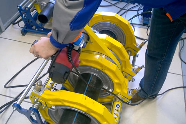
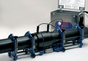
Butt welding polyethylene pipes quite often used during pipeline installation. Popularity this method due to the low cost and speed of work.
General information
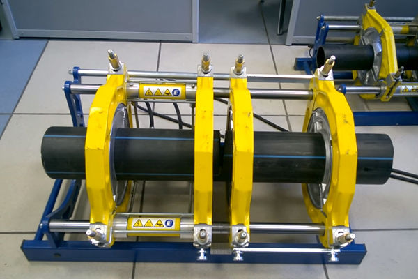
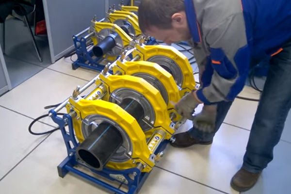
When using this technology, heated pipes are connected under pressure and securely fixed until they cool completely. The strength of the resulting connection is much higher than the strength of the pipes.
Butt welding of polyethylene pipes is used for products with a diameter of 50 mm or more. It is with this diameter that their wall thickness is 5-7 mm, which is the optimal value for a reliable connection. For products with a smaller diameter, this method should not be used.
Types of polyethylene pipes
Butt welding is used to connect different polyethylene pipes, which differ in their density. It is indicated by the numbers after the abbreviation:
- PE32. They have the lowest density and therefore are practically not used anywhere.
- PE63. They are often used for water distribution in private homes or in non-pressure systems. They are used much less often during the creation of sewer systems, since they cope very poorly with strong pressure and quickly break.
- PE80. Can be used both indoors and outdoors. When used outdoors, they should be insulated.
- PE100. These products are the heaviest and most durable. They are used in almost all areas. Quite often used in heating distribution and for the delivery of gases and liquids under high pressure.
Advantages and Disadvantages
Butt welding of polyethylene pipes has many advantages. Using this method allows you to:
- carry out work without large quantity people and equipment - this will require several people and special equipment for butt welding of polyethylene pipes;
- save time - butt jointing is done quite quickly;
- reduce pipeline installation costs.
There are not many disadvantages to this connection method. These include several restrictions:
- the technology of butt welding of polyethylene pipes requires a lot of working space, since it is quite difficult to carry out such work in cramped conditions;
- It is not recommended to connect products of different thicknesses, so you will have to make sure that the workpieces are the same;
- The pipes must be connected so that one of them can be moved.
Some of these restrictions will help you get around.
Workflow Features
First you need to find out the exact parameters for butt welding polyethylene pipes. With their help, it will be possible to correctly configure the welding equipment. You can see the parameters for butt welding of polyethylene pipes in the table.
Parameter table:
Having understood the table for butt welding of polyethylene pipes, you need to prepare the equipment. To work you will need:
- wire cutters;
- roulette;
- heating nozzles;
- soldering iron, which will be used for butt welding of polyethylene pipes;
- mounting bolts for nozzles;
- hole template;
- level that may be needed to determine the inclination of the elements being connected.
It is carried out using various welding equipment:
- Manual. It is used when you need to connect small diameter pipes. Before using the equipment, you must configure it. This is done using a welding table, which indicates all the necessary parameters. The quality of the future welded joint depends on the preliminary settings.
- Semi-automatic. Such units are equipped with special hydraulic systems. When connecting pipeline elements, a centralizer is used, which greatly facilitates the work. Using semi-automatic models, you can connect products of large and small diameters.
- Automatic. All work is carried out under computer control. The welder does not even need to set up the machine in advance, since he does it himself. The use of automatic equipment allows us to completely eliminate errors that often occur during manual connection. Thanks to this, the quality of welding joints is very high.
Welding technology
To correctly connect the pipeline elements, you need to familiarize yourself with the features of this technology. Butt welding of polyethylene pipes is performed as follows:
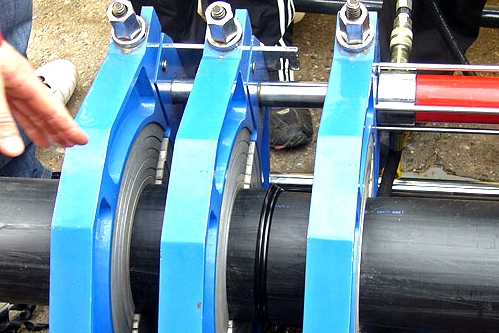
- The workpieces are secured in the centralizer of the welding equipment, after which they are trimmed. Then the products are applied to each other so that you can make sure that there is no strong gap. If products with a small diameter are connected, the gap should be less than 0.4 mm.
- A welding mirror is placed between the workpieces, which should not heat up more than 225 °C.
- The ends of the pipeline elements are pressed against the mirror until a burr appears with a height of about 1 mm. After this, the pressure decreases to 0.3 kg/cm 2 and does not change until completely warmed up.
- After heating, the products are connected to each other. In this case, you need to ensure that the burr is not too large.
- You can remove workpieces from the centralizer only after they have cooled;
- Finally, the pipeline must be checked. To do this, you need to fill it with water and make sure that it does not leak through the joints.
“Pay attention!
Butt welding of HDPE pipes must be accompanied by control of parameters. You need to control the pressure during operation using a pressure gauge. If this is not possible, then this will have to be done visually based on the size and shape of the burr.”
During pipeline installation, it is necessary to take into account that when temperatures change, polyethylene can greatly compress or expand. To compensate for thermal expansion, it is recommended to lay pipes in a snake pattern.
Possible errors
When connecting pipeline elements manually The following errors may be made:
- uneven distribution of burr around the circumference of the joint;
- improper welding of joints, which can lead to their strong displacement;
- poor pressing of the ends, which is why there may be pores and cracks at the joints.
Conclusion
You can install the pipeline yourself using butt welding. To do this, it is enough to study the parameters of butt welding of polyethylene pipes and become familiar with the features of this process.
8 Welding process parameters
It would seem that with the introduction of GOST R ISO 55276, the anarchy ended. Or it will end soon. Only the butt welding modes of polyethylene pipes described in GOST will remain legal on the territory of the Russian Federation.
However, in Europe, in the eternal competition between DVS (German Welding Association) standards and ISO standards, DVS standards often win. Perhaps because the DVS standards are more suitable for direct use. In particular, the preparation of pipes for the welding process is standardized here in numbers - both the permissible mismatch of the pipe walls and the permissible gap between the ends. The temperature of the heated tool (welding mirror) is also described in detail here - depending on the pipe material and wall thickness. And not in the form of a wide acceptable range without explanation.
In our country, DVS standards are also still trusted more. The modes of butt welding of pipes made of PE and PP, regulated by DVS standards, comply with our standards, which have been successfully used for decades - OST 6-19-505-79 and VSN 003-88, etc.
As a result, European manufacturers of butt welding machines by default supply them with welding tables in accordance with DVS standards, and the Russian consumer is completely satisfied with this.
However, it should be borne in mind that butt welding modes according to ISO 21307 in Europe or according to GOST R 55276 in Russia have no less legitimacy than DVS standards. And they ultimately lead to more or less the same result, at least from the point of view of the strength and reliability of the welded joint. It remains only to understand whether it makes sense to give them preference and in what cases.
GOST (and its ISO prototype) describes 3 modes of butt welding - with a single low pressure, with double low pressure, with a single high blood pressure. We are talking about the pressure created in the material of the welded products at the stage of weld formation and cooling. GOST does not explain under what conditions which mode is preferable. Some clarity is provided only by a close study of their features.
8.1 Brief comparison of butt welding modes
8.1.1 First mode - Welding at a single low pressure
This mode of butt welding of PE pipes can be called classic, since it is very close to DVS 2207-1, to all other national technologies of European countries, as well as to the modes ever described in Russian standards. Perhaps this is why its description is more suitable than other welding modes for polyethylene pipes for direct use by the welder.
Significant differences from the other two welding modes described in GOST:
- Compared to the third mode of butt welding, the first mode can be performed on cheaper equipment. Since the regulated welding pressure is only 1.7 kgf/cm2 (in DVS 2207-1 it looks like: 1.5 kgf/cm2). It is simply impossible to go much lower, otherwise it will no longer be possible to ensure welding strength either by lengthening the time or increasing the heater temperature. The lowest welding pressure means there is no need for an insanely strong centralizer and an overly powerful hydraulic unit. The price to pay for this is a slightly longer butt joint welding cycle.
- Compared to the second mode of butt welding, the first mode requires long-term maintenance of pressure during the cooling phase. This allows you to reduce the temperature of the heated tool, reduce the heating time, and most importantly, reduce the overall duration of the butt weld welding cycle.
8.1.2 Second mode – Welding at double low pressure
This mode of butt welding of polyethylene pipes is designed for welding machines that not only cannot provide a welding pressure higher than 1.5 kgf/cm 2, but even such pressure can only be maintained for a short time.
Significant differences from the other two welding modes described in GOST:
- Compared to the third mode of butt welding, the second mode does not require expensive equipment capable of creating high welding pressure.
- Compared to the first mode of butt welding, the second mode does not require long-term maintenance of welding pressure - only 10 seconds at the beginning of cooling. In order for such a short compression to provide satisfactory weld strength, it was necessary to increase the temperature of the heated tool and the heating time.
In our opinion, the second mode of butt welding has no practical value for two reasons: (1) in our long history of selling welding equipment and studying competitors’ equipment, we have never encountered devices that are unable to maintain pressure for a long time, and most importantly (2) the second The butt welding mode in both GOST and the original ISO 21307 is described inconsistently and is hardly suitable for practical use. Therefore, we will not consider it further.
8.1.3 Third mode – Single high pressure welding
This mode of butt welding of polyethylene pipes reduces the duration of butt welding to a minimum, regardless of the increased requirements for equipment. And equipment manufacturers - if you please, comply.
Significant differences from both other butt welding modes described in GOST:
- The third mode reduces the net time of the welding process by 2.0-2.5 times (see clause 8.3). And this is an absolute plus.
- The third mode requires a welding pressure of 4.2÷6.2 kgf/cm 2. This is 3 times higher than the first mode. And 3.5 times higher than DVS 2207-1. This circumstance has two sides to the coin. On the one hand, for welding big pipes(close to the upper limit of the operating range of the welding machine) a much stronger centralizer and a more powerful hydraulic unit will be required. In other words, a more expensive car. But on the other hand, when welding a small pipe (close to the lower limit of the operating range of the welding machine or slightly below the range), the third mode turns out to be a real salvation!
8.2 Comparison of welding parameters for PE pipes at low and high pressure
8.2.1 Heater temperature
Temperature T heated tool is important for two phases of the welding process - phase 1 (melting) and phase 2 (heating). Next, the heated tool is removed from the welding zone and is no longer involved in the process.
The main and only purpose of the heated tool is to heat the ends of the pipes.
The temperature distribution graph along the pipe axis continuously changes throughout the entire welding process. We are now interested in what the temperature of the welded ends will be at the moment of their contact after removing the heated tool (technological pause).
8.2.3 Maximum permissible technological pause time
Allowable duration t 3 The technological pause is limited by two main processes occurring with the heated polymer in air - cooling and oxidation. If you do not meet the regulated time, the ends of the pipes will either not stick together under welding pressure, or the thin layer of material in the weld area will be oxidized and weak.
In hot polyethylene, oxidation is relatively small; the limitation of the technological pause time is determined mainly by the cooling process - unlike, for example, PVC, in which the main damage is caused by oxidation. Thus, for polyethylene, the maximum permissible technological pause time is determined by the cooling rate (depending on the wall thickness) and the minimum permissible final temperature (depending on further welding pressure).
For the first mode of butt welding of polyethylene (low welding pressure), GOST determines the maximum duration of the technological pause in seconds with the formula 0.1 +4, for the third mode (high welding pressure) - 0.1 +8.
DVS 2207-1 gives the maximum duration of the process pause in the form of a table, which can be interpolated with a similar function, maintaining the same principle: the greater the wall thickness, the longer the permissible changeover time.
8.2.4 Welding pressure value
After heating and a technological pause, the temperature distribution along the pipe axis corresponds to the graph in Fig. 25. Where it is hotter, the material is more subject to thermal destruction. And after cooling it will be less durable.
How can you avoid losing the strength of a pipe with a less durable material? There is only one way out - to increase the thickness of the pipe wall in this place.
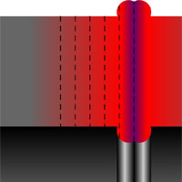 |
If you mentally break the pipe into sections of very short length (Fig. 29), then it will become clear that each section was heated to a very specific temperature, and, accordingly, suffered a very specific deterioration in strength properties as a result of this heating, and requires a very specific relative increase in wall thickness to compensate for this deterioration. To achieve such an uneven increase in wall thickness, the pipes to be welded must be pressed against each other with force until the heated layers have cooled down. Then each section of the pipe will “flatten out” and increase the wall thickness the more, the more it was heated and the more thermal destruction it underwent. Everything is clear, logical and expedient. With what force must the pipes be pressed against each other so that the increase in wall thickness in each section compensates for the deterioration in the strength properties of the material in this section? It is clear that the magnitude of the relative expansion depends on the welding pressure. Those. at the same heating, the high pressure butt welding mode will give a greater increase in wall thickness than the low pressure welding mode. However, it should be remembered that during further cooling, polyethylene retains its elasticity, which decreases with decreasing temperature. And after removing the welding pressure, the wall thickening we achieved will return somewhat. The sooner we remove the pressure, the stronger it will come back. Read more about this in paragraph 8.2.6. |
|---|---|
| Rice. 29 Heating distribution |
Low welding pressure (1.5-1.7 kgf/cm2) is designed to ensure that such pressure will remain in effect until the temperature of the polyethylene drops to 40-45°C.
And the increase in wall thickness at a welding pressure of 4.2-6.2 kgf/cm 2 will be much greater. Then cooling under pressure can be completed much earlier; the residual increase in wall thickness will still be sufficient.
8.2.5 Settling time
After the technological pause, the welding pressure is not achieved instantly, but takes some time, called the upsetting phase, or the pressure rise phase. If only because no drive is capable of performing such work instantly. But there is another reason.
Let us again consider the temperature distribution graph at the moment the pipes touch after a technological pause (Fig. 25). As we can see, a thin layer of material is in a viscous-fluid state, i.e. has a higher temperature T VT. This necessary condition, we specifically strived for this, otherwise the ends of the pipes would not stick together upon contact.
If we now sharp Let's create welding pressure, in this thin layer there will be a particularly strong flow of the extruded material. This flow of material will pointlessly increase the external and internal burrs, which, in particular, will reduce the permeability of the pipeline at the site of the butt weld (Fig. 30).
But the main problem is different. The directional flow of thermoplastic in a thin gap will lead to subsequent directional crystallization of polyethylene, which will reduce the tensile strength of the pipeline along the pipe axis.
In short, significant flow of material in a thin gap cannot be allowed. This means that full welding pressure can only be applied when our hottest thin layer of material has cooled a little. Namely, when it has time to transfer some of the heat to neighboring layers of material (Fig. 31).
This heat redistribution takes a matter of seconds. Obviously, the greater the thickness of the pipe wall and, accordingly, the greater the depth of heating of the ends and the thicker the layer of viscous-flowing material, the longer this heat redistribution takes. For the first mode of welding polyethylene pipes (low welding pressure), GOST R ISO 55276 defines it in seconds with the formula 0.4 +2.
However, there is the opposite danger. If the welding voltage is created with a long delay, its magnitude may be insufficient to thicken the cooled wall. And this danger is worse than the possible increase in burr and directed crystallization. Therefore, GOST calls the specified precipitation time “maximum”.
8.2.6 Cooling time
When we compress the pipes in phase 4 (upsetting) with force F 5 and maintain the created welding pressure during phase 5 (cooling), the nature of the deformation of the material in the heating zone is both plastic (irreversible) and elastic (reversible). Under the influence of welding pressure, the pipe wall thickens, continuing to elastically resist the force F 5.
If at some point we remove the compressive force F 5, our deformation will noticeably return (Fig. 32).
The later we remove the clamping force, the less our deformation will return. This is explained simply. As the thermoplastic cools, the van der Waals forces acting between the links of neighboring macromolecules begin to dominate over the forces of thermal vibration of the links. We can simply say that the material hardens in the position in which it is forcibly held.
To what temperature must the material be cooled so that the compressive force can be removed? F 5 and not be afraid that the deformation will come back too much? It all depends on how large the deformation was created in the beginning, i.e. what welding pressure caused it. If the increase in wall thickness was initially created by low welding pressure (1.5-1.7 kgf/cm2), then there is practically no reserve; it will have to be cooled to a temperature of 40-45°C. For the first welding mode of polyethylene pipes (low welding pressure), GOST determines the minimum permissible cooling time in minutes with the formula +3.
And if initially the increase in wall thickness was caused by high welding pressure (4.2-6.2 kgf/cm2), then, according to GOST, cooling under pressure can be completed in (0.43) minutes, the residual thickening of the wall will still be sufficient to compensate for thermal degradation, possible mismatch of pipe walls and possible operator errors. This is where the time savings of the third welding mode come from.
Next general rule for any welding modes: in no case should you try to speed up the cooling process by pouring water over the welded joint area or by other methods. This will lead to the creation of internal stresses in the material and, as a result, to a general weakening of the welded joint. To clearly illustrate how this works, let’s take a hot polyethylene plate and mentally divide it into 2 layers - upper and lower (Fig. 33). If we now pour water on top of the plate, the top layer will quickly cool down. Since polymers have a high coefficient of thermal expansion, the top layer will shrink in size as it cools. The bottom layer is still hot and soft, it does little to prevent the outer layer from shrinking; instead, it itself, without much resistance, reduces its length and increases its thickness. Therefore, the plate will bend down very slightly.
Now the bottom layer begins to cool. As it cools, it also tends to shrink in size. However, the cooled solid top layer elastically resists the reduction in length. As a result, the plate will bend upward very noticeably.
But there is no way for the pipe wall (including in the weld area) to bend. If cooled with water, it will retain its shape, but the inner layer will be stretched like a spring. This greatly weakens the pipe wall. True, in fairness it should be said that in polyethylene internal stresses disappear very quickly. In 2-3 years there will be no trace of them left. Unless during this time the water (or gas) pressure inside the pipe breaks our weld, weakened by internal stresses.
8.2.7 Reflow pressure; primary roller height
Now let's go back to the beginning of the welding process.
When the pipe end first touches the welding mirror, it is necessary to achieve full thermal contact between the surfaces of the pipe end and the welding mirror as quickly as possible. The only way to do this is to press the pipe against the welding mirror with considerable force so that the material being melted begins to flow and displace air from the voids. In this case, a certain amount of molten material is squeezed out along the entire perimeter of the pipe end in the form of external and internal burrs, which is clear evidence of the “fit” of the surface of the pipe end to the surface of the welding mirror (Fig. 18).
Long-developed butt welding modes (including DVS) were picky about the shape of the resulting primary bead; this shape indirectly determined the pressure at which it was created. The primary bead in the shape of a sharp petal (Fig. 34) indicated that the pressure was too high during the first phase of welding and was considered an error.
Indeed, old single-modal grades of polyethylene behaved exactly this way, and the sharp petal, in theory, created a “stress concentrator” in the inner corner. However, modern bi- and polymodal grades of polyethylene are distinguished by a smooth thermomechanical curve; their fluidity increases more smoothly with increasing temperature and pressure. The shape of the primary roller at a pressure clearly exceeding 1.5-1.7 kgf/cm 2 can be the most unexpected, from a drop to a flat column. As a result, the shape of the primary bead was left alone, and at the same time, any pressure during the melting phase of the ends was no longer considered an error.
Now the logic when choosing the reflow pressure is as follows. Little pressure is not advisable, otherwise the formation of the primary bead will take too long. In addition, from the point of view of ease of control of the welding machine, it is easier to set the control valve once to a certain welding pressure before starting to weld a butt seam, and then use this pressure both when melting the ends and when forming the weld.
It is interesting that for the third mode of butt welding (high welding pressure), the size of the primary bead is not defined in GOST. But the size of the roller that should be obtained at the end of heating is determined (again, in millimeters): 0.15 +1. This is one of the reasons why the welder cannot directly use the description of the high pressure butt welding mode - it is impossible to understand at which primary bead to finish melting (relieve pressure) in order to obtain a bead of the prescribed size at the end of heating. We can make the assumption that when heated, the size of the bead increases slightly, and we can focus on the indicated size of the secondary bead already during melting. However, we'll leave it to the developers technological maps welding of polyethylene pipes.
8.2.8 Heating pressure
The main task of the heating phase is to heat the ends of the pipes to the required depth. This means that the heating pressure must be low enough that the size of the roller does not increase any further. In theory, the pressure should be zero.
But this is only in theory. In practical applications, zero heating pressure may result in inadvertent loss of contact between the pipe end and the heater. Especially if the displacement pressure is small and/or if the displacement pressure is determined not by friction (or not only by friction), but by the pipe sliding down an inclined slope.
The theoretical part of the description of both procedures in GOST recommends heating pressure in the range from 0 to displacement pressure. However, the example given below in GOST sets the heating pressure at 0.25 kgf/cm 2 above the displacement pressure, and this value is suitable for practical use.
8.3 Comparison of welding times at low and high pressure
To evaluate the gain in welding time for polyethylene pipes, which provides the third mode of butt welding (at high pressure) compared to the first mode (at low pressure), let’s try to compare the welding time under different modes for pipes with the same wall thickness.
In this case, we do not take into account the melting time, the technological pause time and the upsetting time. These times are small and not fully defined. And most importantly, they introduce a multidirectional “addition” to the total welding duration (melting is shorter at high pressure, and the technological pause and upsetting are shorter at low pressure), so for a rough comparison of the two procedures they can be neglected.
|
Welding process |
Wall thickness |
Heating time |
Cooling time |
Total time |
|---|---|---|---|---|
|
Low pressure | ||||
|
High blood pressure | ||||
|
Low pressure | ||||
|
High blood pressure | ||||
|
Low pressure | ||||
|
High blood pressure |
We see that for pipes with a small wall thickness, the butt welding mode at high pressure gives a gain in joint welding time by more than 2.5 times. For medium thicknesses - approximately 2 times. For large thicknesses - a little less than 2 times.
This is only the pure time of welding the joint of polyethylene pipes. If we take into account the preparation time for welding a joint - fixing pipes, trimming, checking alignment, etc. - we, however, get an estimated time difference of 1.3-1.6 times. In other words, where traditional butt welding technology can make 10 joints per day, a high pressure welding procedure can make 13-16 joints.
CONCLUSION: Taking into account that the cost of equipment for butt welding using traditional technology and similar equipment for welding at high pressure differs by approximately 1.2-1.3 times, welding at high pressure makes direct sense.
There is also an opinion that high welding pressure will make it possible to cope with the “whims” of non-draining grades of polyethylene. However, this is still only a hypothesis.
ATTENTION! We are accustomed to the fact that upon completion of welding using traditional technology (at low pressure), the weld has already cooled down to 40-45°C and is not afraid physical activity. When using the third welding mode (at high pressure), it should be remembered that after cooling under pressure, the welding zone is still quite hot, so the pipeline, after being removed from the centralizer, requires careful handling for some time.
Annual (since spring 2014) experience in sales of equipment for welding polyethylene pipes at high welding pressure has shown that Russian consumers are in no hurry to switch to it en masse, but still prefer machines for butt welding using traditional technology. The author sees two possible reasons for this:
- The butt welding mode at high welding pressure is designed only for polyethylene pipes, while for butt welding of polypropylene, PVDF and PB pipes, the most popular are still the DVS welding modes with low welding pressure. And the implementation of these welding modes is inconvenient on machines with excessively powerful hydraulics.
- In any responsible business, innovations are perceived with caution. Mainly due to lack of information.
Butt welding with a heated tool involves heating the ends of pipes or parts to be welded to the viscous flow state of polyethylene in direct contact with the heated tool and then connecting the ends under upsetting pressure after removing the tool.
The main parameters of the butt welding process are:
– temperature of the heated tool Tn;
– duration of melting t op and heating t n;
– pressure of the heated tool on the ends during melting P op and heating P n;
– duration of the technological pause between the end of heating and the beginning of precipitation t p;
– pressure on the ends during upsetting Р ос;
– cooling time of the welded joint under upsetting pressure t cooling;
For machines with a medium and high degree of automation, an additional standardized parameter may be the time of rise of upsetting pressure t D
The change in parameter values over time during the welding process is carried out according to the cyclogram, Fig. 7.
Technological welding parameters are selected according to tables 1 – 4 in accordance with the grade of polyethylene from which the pipes and parts are made.
The temperature of the working surface of the heated tool is selected according to Table 4 depending on the material of the pipes being welded (PE 80, PE 100).
Reflow duration t op. , as a rule, is not standardized and depends on the appearance of the primary burr.
Melting and heating of the ends of the welded pipes and parts is carried out simultaneously (synchronously) through their contact with the surfaces of the heated tool.
Melting of the ends must be carried out under pressure
R op = 0.2 ± 0.02 MPa
(2,0±
0.2 kgf/cm 2), during a time t op sufficient for the formation along the entire perimeter of the pipe ends in contact with the heater of rolls of molten material (primary flash) with a height of at least:
– 1.0 mm with pipe wall thickness from 5 to 10 mm;
– 1.5 mm with pipe wall thickness from 10 to 12 mm;
– 2.0 mm with pipe wall thickness from 12 to 20 mm;
– 2.5 mm with pipe wall thickness from 20 to 26 mm;
– 3.0 mm with tube wall thickness from 26 to 35 mm.
After the appearance of the initial burr, the pressure must be reduced to Р n = (0.02±0.01) MPa (0.2 ± 0.1 kgf/cm 2) and heat the ends for a time t n, which, depending on the assortment (wall thickness) of pipes, ambient air temperature T o should be selected according to the table. 5.
Table 4.
Temperature of the working surface of the heated tool, ºС
Table 5.
Heating time of pipe ends t n, s, from PE80 and PE100
| Ambient air temperature То, ºС and warm-up time, s | ||||
| From minus 15 to 0 | From 0 to 20 | From 20 to 45 | ||
| SDR 11 | 63x5.8-75x6.8 | 75-110 | 60-105 | 50-.95 |
| 90x8.-110x10.0 | 100-140 | 85-140 | 70-125 | |
| 125x11.4-140x12.7 | 120-170 | 100-165 | 80-150 | |
| 160x14.6-180x16.4 | 155-210 | 135-200 | 105-185 | |
| 200x18.2-225x20.5 | 190-260 | 160-250 | 125-225 | |
| 250x22.7-315x28.6 | 250-360 | 225-350 | 210-310 | |
| SDR 17.6 | 90x5.2-110x6.3 | 70-105 | 55-100 | 45-90 |
| 125x7.1-140x8.0 | 95-125 | 80-120 | 60-110 | |
| 160x9.1-180x10.3 | 105-140 | 90-140 | 70-125 | |
| 200x11.4-225x12.8 | 120-170 | 100-165 | 80-150 | |
| 250x14.27-315x18.5 | 135-200 | 115-190 | 90-180 |
It is allowed to reduce the pressure Рн to a minimum while maintaining constant contact of the ends of the pipes (parts) with the heated tool.
The duration of the technological pause required to remove the heated tool should be minimal, no more than:
– 3 s – for pipes Ø 63 mm;
– 4 s - for pipes from Ø 90 to 140 mm;
– 5 s - for pipes from Ø 140 to 250 mm;
6 s – for pipes from Ø 250 to 315 mm.
After removing the heated tool, the ends of the pipes or pipes of the parts are brought together and the joint is upset under pressure P os = (0.2±0.02) MPa (2.0±0.02 kgf/cm2). The joint should be settled by gradually increasing the pressure to a given level. The time of rise in upsetting pressure t d, s, for pipes made of PE 80, PE 100, should be taken according to Table 6.
Cooling of the joint must be carried out under precipitation pressure during the time t cooling. , the value of which is taken from the table. 7. depending on the wall thickness of the pipes and parts being welded and the ambient temperature T o.
Table 6.
Upsetting pressure rise time t d, s, for pipes made of PE80, PE100
| Range of welded pipes according to GOST R 50838 | Timet d, s | |
| Standard dimensional ratio | Pipe diameter and wall thickness, mm | |
| SDR 11 | 63x5.8-75x6.8 | 3-7 |
| 90x8.2-110x10.0 | 4-8 | |
| 125x11.4-140x12.7 | 4-11 | |
| 160x14.6-180x16.4 | 6-12 | |
| 200x18.2-225x20.5 | 8-14 | |
| 250x22.7-315x28.6 | 10-16 | |
| SDR 17.6 | 90x5.2-110x6.3 | 3-6 |
| 125x7.1-140x8.0 | 4-7 | |
| 160x9.1-180x10.3 | 4-8 | |
| 200x11.4-225x12.8 | 5-10 | |
| 250x14.27-315x18.5 | 8-12 |
Table 7.
Joint cooling time tcool., min, not less, for pipes made of PE80 and PE100
| Range of welded pipes according to GOST R 50838 | Ambient air temperature То, ºС, and warm-up time, s | |||
| Standard dimensional ratio | Pipe diameter and wall thickness, mm | From minus 15 to 0 | From 0 to 20 | From 20 to 45 |
| SDR 11 | 63x5.8--75x6.8 | 4-5 | 5 -6 | 6-7 |
| 90x8.2--110x10.0 | 6-7 | 7-8 | 8-9 | |
| 125x11.4--140x12.7 | 8-11 | 10-13 | 12-15 | |
| 160x14.6--180x16.4 | 11-14 | 13-16 | 15-18 | |
| 200x18.2--225x20.5 | 16-21 | 18-23 | 20-25 | |
| 250x22.7--315x28.6 | 24--30 | 26-.32 | 28-36 | |
| SDR 17.6 | 90x5.2--110x6.3 | 4-5 | 5-6 | 6-7 |
| 125x7.1--140x8.0 | 5-6 | 6-7 | 8-9 | |
| 160x9.1--180x10.3 | 8-10 | 9-12 | 10-12 | |
| 200x11.4--225x12.8 | 10-11 | 11-13 | 13-15 | |
| 250x14.27--315x18.5 | 18-22 | 19-24 | 21-28 |
In order to increase the accuracy of maintaining specified pressures (P op., P n, P os) during the welding process, it is necessary to take into account the friction losses of the moving parts of the welding machine and the pipe (section) moved during welding. To do this, before welding each joint, the force is measured at idle speed of the movable clamp of the centralizer of the machine with the pipe (section) fixed in it, which is summed up with the force necessary to create the specified pressures (P op., P n, P os).
When welding with a heated tool, the working surfaces of the heater are covered with an anti-adhesive layer that prevents the melt from sticking to the tool.
The parameters of the process cyclogram (Figure 7) and welding modes (Tables 4 - 7) of pipes of various assortments are observed automatically by a welding machine with a high degree of automation; with a medium degree of automation - some of the parameters are performed in manual mode; in manual welding machines, only the temperature of the heating tool is automatically maintained .
Marking of welded joints (operator code) is carried out with an indelible pencil marker bright color(for example: white or yellow - for black pipes, black and blue - for yellow pipes).
The marking (joint number and operator code) is applied next to the joint on the side closest to the factory marking of the pipes.
It is allowed to mark (operator code) with a stamp on the hot melt of the flash 20-40 s after the end of the upsetting operation during the cooling of the joint in the clamps of the centralizer of the welding machine at two diametrically opposite points. It is recommended to use stamps of type PU-6 or PU-8 according to GOST 2930.
When performing work, carry out systematic operational control of the quality of assembly for welding and welding modes;
Preparation for work and work order. At the work site, fix the pipes to be welded in the fixed and movable clamps of the welding block. The ends should protrude from 15-20 mm. Shaped profile parts, transitions and bushings are fixed only in a movable clamp, in special inserts, which are supplied with the welding unit and are installed instead of inserts 14. (Fig. 4). When moving from a pipe of a larger diameter to a smaller one, first weld the adapter sleeve to the pipe of a smaller diameter. Install a trimming device onto the cylinder rods and secure. Using handle 10 (Fig. 4), press the ends of the fixed pipes tightly against the trimming device. By turning the handle of the trimming device, the ends of both pipes are trimmed. Simultaneously with pipe trimming, the heater is heated (the heater surfaces must be cleaned of deposits with a scraper).
Its heating temperature is controlled automatically. The indicator remains in the heater until X until the arrow on its scale stops within the marked sector, while for pipes made of medium-density polyethylene PSP the arrow should be at the beginning of the sector (TH-230-240º C), and for pipes made of high-density polyethylene PVP at the end of the sector ( TN-250-260º C). After determining the temperature, the indicator is removed from the heater hole and inserted into the bracket provided on the burner casing. Then the heater is installed in the gap between the processed ends of the products. By moving the movable clamp manually using a manual movement mechanism, the ends are pressed to the planes of the heater.
The hydraulic system valve is closed and the required pressure is created by the pump. After the ends have melted, the pressure in the hydraulic system is quickly released and the pump creates the pressure necessary for warming up. After warming up, the pressure is released again. To do this, you need to open tap 19 (Fig. 4) and remove the heater. The pipes are quickly brought into contact using a manual drive, the valve is closed and the required pressure is created by pump 11.
Pressure control is carried out using a pressure gauge with maximum deviations of 20%. The pressure gauge readings should be the sum of two values according to the formula:
R slave = R calculated + R cold. progress
where R slave. – working pressure, kgf/cm2; P calculation – the pressure required to create a pressing force on the surfaces being welded during melting, heating or upsetting of the material, kgf/cm 2. It is selected depending on the diameter and type of pipes being welded according to Table 4.
R cold stroke – the pressure in the system necessary to overcome the friction forces in the movable clamp (idling force), kgf/cm 2. It is determined after 200 hours of operation of the installation, because this value depends on the condition of the rubbing surfaces.
After welding, the pipes must be kept in the clamps of the welding unit for 5-7 minutes to cool, after which the pipes are released from the clamps and the installation moves to the place where the new joint is welded. It is permissible to trim pipes as follows. Using a hydraulic system, bring the ends of the pipes to the trimming device, ensuring optimal pressure for removing chips, and continue trimming until the chips stop coming out. If necessary, press the ends of the pipes to the trimming device and repeat the trimming.
Equipment and materials
1. Installation for welding with a heated tool, the schematic diagram of which is shown in Fig. 4.
2. Blanks from thermoplastic pipes measuring 63×5.8 mm (one of the materials is polyethylene, vinyl plastic, plexiglass) – 10 pcs.
3. Tensile testing machine up to 15000N , equipped with special grips.
4. Tools for making samples: template, scriber, hacksaw, semicircular file, caliper, scraper.
Work order
1. Read the instructions for using the mobile installation for welding polyethylene pipes.
2. Carry out trial welding of one workpiece in order to check the operation of the installation and gain the skill of setting it up for a certain mode.
3. Mark and measure the sections being welded to calculate the required amount of force during welding. Enter the data into the table. 8.
4. Weld the workpieces at four to five different values of one of the parameters and constant values of the others (as directed by the teacher).
When fastening pipes in clamps, pay attention to the correct installation of the workpieces. Do not allow the edges to move.
5. After cooling the weld (cooling time is at least 1 min), release the workpieces from the upper clamps, move the movable clamp to its original position and remove the workpiece from the installation.
6. Conduct a visual inspection of the resulting welded joint. Criteria for assessing the appearance of joints made with a heated butt tool are given in Table 26 of Appendix A.
Table 8
Measurement results
| Item no. | Workpiece material | Dimensions of workpieces before welding | Welding mode | Breaking force, N | Tensile strength, MPa | Relative strength, % | Nature of destruction | Burr shape and size, mm | |||||||||
| Width | Height | ||||||||||||||||
| Thickness, cm | Average diameter, cm | Area, cm 2 | Tool temperature, ºС | Time, s | Pressure, MPa | ||||||||||||
| Reflow | heating | Reflow 0.2±0.02 | Heating 0.02±0.01 | ||||||||||||||
Self-test questions:
1.What are the types of butt welding of thermoplastics with a heated tool?
2. Components of a installation for welding polyethylene pipes?
3.What are the main parameters of the butt welding process?
4. Cyclogram of the process of butt welding with a heated tool for polyethylene pipes?
5. Depending on what is the temperature of the working surface of a heated tool selected?
6. On what factors does the heating time of the pipe ends during NI welding depend?
7. What factors determine the cooling time of the joint?
8. What is a technological break?
9. On what factors does the technological pause time depend?
10. What is the pressure when the ends of the pipes melt?
11. What is called grate?
12. What height should the primary burr beads be when the pipe wall thickness is from 10 to 12 mm?
This article describes the technology for welding polyethylene pipes, as well as pipes made of plastic, PVC and other polymer materials. Special attention devoted to the following issues:
DEFINITION OF WELDING
C welded joints are permanent, i.e. cannot be disassembled without breaking parts. This indicates the solidity (continuity) of the welded joints. Such monolithicity can be ensured if interaction forces (van der Waals forces) arise between the surface macromolecules of the parts being connected and their mutual movement occurs from one part to another, for example due to diffusion.
It would seem that it is enough to bring the surfaces together at such distances (0.3-0.4 mm) at which these forces begin to noticeably manifest themselves so that bonds arise between the surface macromolecules of the plastics being welded, the interface disappears, and welding occurs. It is these considerations that some authors are guided by, defining welding as a technological process for obtaining a permanent connection of parts of a product, based on mutual diffusion and chemical interaction of polymer macromolecules, as a result of which the interface between the joined surfaces disappears.
However, even in the ideal case, when there are no microroughnesses on the surfaces to be joined (ideally smooth surfaces), various contaminants, adsorbed gases and other components that prevent such rapprochement, external deformation and thermal energy is required. Deformation energy will be spent on overcoming the repulsive forces that arise between the approaching surface atoms. Thermal energy increases the likelihood of interaction between them. If we proceed from such ideas, then in the welding zone two main processes can be distinguished: the first is the supply and transformation of energy and the second is the movement (or transformation) of matter. The intensity of the energy conversion process and its nature determine the type of welding.
To implement welding process activation of the welded surfaces is necessary. This is achieved by supplying and, in some cases, converting energy. The introduction of the substance is necessary only for certain types of welding of plastics, for example when welding with heated gas using filler material, as well as when welding with a melt. In the latter case, energy is supplied with the filler material and the melt.
Movement of matter under different types welding of plastics may be significant. It is caused by mixing and diffusion occurring in the material heated to a viscous flow state. A special type of movement should be considered a chemical reaction of active groups located on the surfaces being welded, with each other or with active groups of an intermediate substance, which can also occur when energy of one kind or another is supplied (chemical welding).
Based on the above, we can assume that in a thermodynamic sense there can be no difference in the definition of welding of plastics and metals. This definition can be formulated as follows: welding is the process of obtaining a monolithic joint of materials through the introduction and thermodynamically irreversible transformation of energy and matter at the joint.
MECHANISM OF THE WELDING PROCESS AND WELDABILITY OF PLASTICS
According to modern ideas, welding process should be considered as a topochemical reaction, i.e. chemical reaction occurring on a surface solid. The basis of any chemical reaction is the process of breaking bonds in the original substances and the formation of new bonds, leading to the formation of a new substance. Thus, the mechanism of joint formation should not change when moving from one welding method to another and from one material to another. Only the set of phenomena on the contact surfaces changes, bringing them into a state of interaction. These phenomena can be different and are determined by the nature of the material and the welding method.
A topochemical reaction is characterized by three stages: the formation of physical contact; activation of contact surfaces; volumetric development of interaction.
The formation of physical contact usually occurs when pressure is applied to the parts being welded. In some cases, when molten filler material enters the welding zone, physical contact between it and the welded edges can be carried out without applying pressure or at a relatively low pressure. This applies to hot gas welding and extrusion welding.
Establishing physical contact between the surfaces to be welded can precede heating, be carried out after heating the surfaces to be joined to welding temperatures, or simultaneously with heating. In any case, at this stage there is plastic deformation macro- and micro-irregularities, due to which the contacting surfaces come closer together. The work of deformation is also spent on removing foreign inclusions (gas bubbles, oil and grease stains and other contaminants) from the contact zone. For soft plastics and fibrous materials, compaction is characteristic at this stage, manifested in a decrease in the thickness of the material.
Activation of the surfaces to be welded involves heating them to increase the energy of thermal movement of macromolecules. Heating can be carried out either directly by transferring heat from a heated tool, gas or filler material to the parts being welded, or by converting other types of energy into thermal energy. This can be the mechanical energy of ultrasonic vibrations or friction, the energy of a high-frequency electric field of a capacitor, electromagnetic energy, the energy of infrared radiation, a laser and a concentrated light beam.
When welding using transformation various types energy into thermal thermal activation of surfaces will be preceded by processes associated with the specifics of this type of welding: displacement of dipoles - when welding with currents high frequency; input and propagation of ultrasonic vibrations, as well as energy concentration and conversion mechanical vibrations V thermal energy- during ultrasonic welding; absorption of radiant energy - when welding with infrared radiation.
The stage of thermal activation can also be accompanied by the development of deformation processes, since the action of static, and during ultrasonic welding and dynamic loads leads to the penetration of the tool into the surface of the part in contact with it, as well as to the displacement of plasticized or molten material from the welding zone.
The volumetric development of interaction is accompanied by a number of complex physicochemical processes, among which the most significant are diffusion, flow and physicochemical transformations. The theory of welding, in which the dominant role at this stage is given to diffusion, is called diffusion. The theory, in which it is believed that flow processes are responsible for weldability, is called rheological ~ after the name of the science of rheology, which studies the laws of flow.
According to the diffusion theory, in order to obtain a compound, it is necessary that when two surfaces of a substance come into contact, a sufficiently complete fusion (coalescence) occurs.
Complete coalescence of two layers of liquid occurs upon their direct contact and is accompanied by the disappearance of the interface between them. In the case of joining polymers, one contact is not enough for coalescence, since structure formation in the contact zone must still occur, which can be achieved through the diffusion of macromolecules as a whole or individual segments. The movement of the segments is prevented by their connection with the rest of the macromolecule, so the diffusion of the segments causes some change in the configuration of the chain molecule. As a result, a large number of successive movements of segments will lead not only to a change in the shape of macromolecules, but also to a displacement of their centers of gravity. The movement of segments and macromolecules as a whole is called micro-Brownian and macro-Brownian motion, respectively.
The movement of entire macromolecules can occur especially easily if the contact of the polymer layers occurs at a temperature above the flow temperature. In this case, a structure characteristic of a polymer appears relatively easily in the contact zone. Diffusion of individual segments of macromolecules can also occur at temperatures corresponding to the highly elastic state of the polymer, while the movement of the molecule as a whole is difficult. At such temperatures, the degree of coalescence is less than unity (the maximum degree of coalescence is equal to unity and is observed only in liquids), which is explained by the fact that after moving the segments to a certain depth, diffusion stops due to stresses arising in the molecular chains.
Proof of the diffusion nature of the welding process can be the fact that all measures that promote thermal movement (increasing pressure and temperature, introducing plasticizers, etc.) cause an increase in the strength of the welded joint and, conversely, factors slowing down diffusion reduce the strength.
Proponents of the rheological theory point out that if only diffusion were responsible for the formation of the joint, then the welding time would be tens of minutes. However, in practice this time is much shorter. In addition, it should be taken into account that the diffusion process is inevitably hampered by air gaps and contamination of the surface layers of the materials being welded, so the penetration time increases even more. Finally, it should be borne in mind that the diffusion coefficient does not remain constant, but continuously decreases, since as sections of macromolecules penetrate through the interface, their inhibition continuously increases.
Therefore, supporters of the rheological theory suggest that the manifestation of the forces of intermolecular interaction and diffusion in contacting volumes is preceded by a number of phenomena associated with the flow and mixing of the melt (1-4, 16).
It is believed that when molten surfaces come into contact, the stresses created by the clamping force (and in ultrasonic welding, dynamic stresses) cause a shift in the layers of the melt. With such a shift, the air gap and other foreign inclusions are removed from the joint zone, and the melt is squeezed out of the welding zone, which indicates that a high-quality welded joint has been obtained. The shear rate in different areas of the contacting surfaces may vary due to the uneven distribution of temperatures and stresses. All this can lead to mixing of the melt in contacting volumes, which is especially likely in cases of welding using high-frequency mechanical (ultrasonic welding) or electrical (High-frequency welding) vibrations.
The phenomenon of mixing of viscous-flowing material in the welding zone was confirmed experimentally when studying the process of welding plastics with a heated tool. Apparently, macro-volumes of viscous-flowing material during welding are characterized by a mixing process, and micro-volumes are characterized by a diffusion process.
If welding is carried out in the highly elastic temperature range, the diffusion mechanism is predominant. In this case, long-term contact of the welded surfaces with each other is necessary, the welds maintain the interface, and the material in the joint zone does not differ from the original in supramolecular structure. Such welding occurs at significant pressures, which causes significant residual stresses in the weld zone after cooling the joint [7-10].
If welding is carried out in the viscous flow temperature range (for amorphous polymers) or in the melting temperature range (for partially crystalline polymers), the process is similar to metal welding. Under the influence external forces rapid coalescence of the melt occurs, accompanied by movement and mixing of layers. In this case, melt layers containing gas and oxide inclusions are removed from the welding zone, which facilitates further mutual diffusion of sections of molecular chains and entire macromolecules in microvolumes. IN welds In such connections there is practically no interface between the surfaces being connected. They do not collapse along the initial plane of contact, and the supramolecular structure can change depending on the cooling conditions of the melt 19-11.
Due to the fact that fusion welding at the final stage is associated with the flow of the melt, the weldability of plastics is assessed by such characteristics as the activation energy of the viscous flow, the temperature range of the viscous flow state and the viscosity of the melt. In the light of these ideas, it becomes obvious that the lower the activation energy of viscous flow and the viscosity of the melt and the larger the temperature range of viscosity-flow, the more likely the formation of a high-quality welded joint. Based on their rheological properties, plastics can be divided into three groups (1, 4, 10, 16, 18, 19).
The first group includes non-oriented thermoplastics, in which the activation energy of viscous flow is significantly less than the chemical bond energy and does not exceed 150 kJ/mol; the temperature range of the viscous-flow state (Tt and Tr where Tt is the fluidity temperature, and Tr is the decomposition temperature) exceeds 50 °C; melt viscosity is 102-105 Pa. With.
When heated, such thermoplastics transform into a viscous-flow state without thermal destruction and remain in a viscous-flow state over a fairly wide temperature range; in this case, the viscosity of the melt is such that with little effort its rapid and complete coalescence can be ensured. These thermoplastics are well welded by fusion welding using various welding methods in a wide range of conditions. The most typical representatives of this group of thermoplastics are polyolefins.
The second group includes oriented thermoplastics with the above rheological properties; non-oriented and oriented thermoplastics with high activation energy of viscous flow (close to the chemical bond energy); thermoplastics with a narrow range between the fluidity temperature and the decomposition temperature (less than 50 ° C) and a relatively high melt viscosity.
For thermoplastics with a high activation energy of viscous flow, there is a danger of destruction when heated to a viscous flow state. Thermoplastics with a narrow temperature range between Tt and Tp can decompose with slight overheating. In oriented thermoplastics, when heated to a viscous-flow state, the oriented structure, which ensures the strength of the material, is inevitably disrupted. For thermoplastics with high melt viscosity, it is difficult to ensure complete melt coalescence and mixing.
Such thermoplastics can be fusion welded only under certain mandatory conditions. For oriented materials and materials with a narrow interval between Tt and Tp, fusion welding should not cause misorientation and destruction of the material, which is only possible under the condition of rapid and local heating to the fluidity temperature of the surfaces being welded without penetration of the material throughout the entire thickness. As for thermoplastics with melt viscosity above 105 Pa. s, then their fusion welding is possible only if the viscosity of the melt is reduced during the welding process. Therefore, to ensure the possibility of fusion welding of thermoplastics belonging to this group, it is necessary in each specific case to find optimal welding methods and techniques.
This group includes polyvinyl chloride, polyvinylidene chloride, pentaplast, polyethylene terephthalate, polycarbonate, fusible fluoroplastics and other thermoplastics.
The third group includes thermoplastics whose viscous flow activation energy exceeds the chemical bond energy, as well as thermoplastics with a melt viscosity of 1011 - 1012 Pa. C. These thermoplastics cannot be converted into a viscous flow state, i.e. cannot be fusion welded. These include, for example, fluoroplastic-4, cellulose acetate, polyvinyl acetate. The formation of compounds of such thermoplastics is possible only by the mechanism of diffusion welding with heating of surfaces to temperatures of a highly elastic state, with long exposure under pressure equal to the limit of forced elasticity of the materials being welded, at the highest possible temperature.
Acceleration of diffusion welding can be achieved by using solvents in which this thermoplastic is able to swell and dissolve. Solvents increase the mobility of macromolecules, so the welding temperature can be reduced.
WELDING WITH DIRECT HEATING DURING INSTALLATION OF PIPELINES
Butt welding of pipes
P plastic pipelines received in recent years widely used both in our country and abroad. Such widespread use of plastic pipelines is due to the fact that they are 4-5 times lighter than steel ones, exhibit high resistance to aggressive environments and have lower hydraulic resistance. Labor costs for installation and operation of pipelines made of plastics are on average 2 times less than pipelines made of high-quality carbon steels, and 3-4 times less than pipelines made of stainless steels.
The most commonly used pipes are low- and high-density polyethylene, polypropylene and polyvinyl chloride pipes with a diameter of up to 315 mm. In the near future, it is planned to use high-density polyethylene pipes with a diameter of up to 630 mm. The main type of connection of such pipes during pipeline construction is butt welding.
Table 4.1. Approximate values of the parameters of the welding mode of some thermoplastics with a heated tool (direct heating)
* Light stabilized with carbon black.
High quality of welded joints of plastic pipelines is ensured by carrying out a set of control measures at various stages of production. This complex includes three stages: preventive control (before the start of welding), active (during the welding process) and acceptance control (after completion of welding).
Preventive control includes quality control of welded materials, selection of welding equipment taking into account its performance indicators, checking the qualifications of welders and control of technological preparation of production.
When arriving at the warehouse, it is necessary to sort the pipes so that pipes with similar geometric parameters are received for assembly. On their surface and at the ends there should be no cracks, bubbles, cavities and foreign inclusions visible to the naked eye, no traces of cold junctions and decomposition of the material.
The storage conditions for pipes should prevent direct exposure to sun rays, since in this case not only a decrease in the strength of the pipe material is possible, but also a significant deterioration in their weldability.
Before welding, pipes are subjected to mechanical and thermomechanical tests.
The guaranteed shelf life of pipes is two years from the date of manufacture. After the specified period, the pipes must be re-inspected before use.
Preparation of pipes for assembly and welding is of great importance. The inner and outer surfaces of the ends of the pipes being welded at a distance of at least 30 mm from the end are cleaned of dust, oil, carbon black and other contaminants that negatively affect weldability and cause cracking of the weld during operation. The connected surfaces of the pipes clamped in the welding installation are subjected to trimming after cleaning. The chips formed during trimming are removed with a clean rag or another method that prevents contamination of the ends of the workpieces. In some cases, degreasing of the welded ends with a solvent (acetone, alcohol) is used. Deformed, torn or nicked pipe ends are cut off. The cutting tool must be degreased before processing edges. It is prohibited to use cooling emulsions and lubricants.
The next important operations are assembling and aligning the pipes before welding. These operations must be carried out on a special device or installation on which welding will be carried out. The ends of the joined pipes must be secured in ring clamps (centralizers) of the welding installation so that the pipe extension is 60-70 mm. After assembly, between the machined ends of the pipes brought into contact, there should be no gaps exceeding 0.5 mm for pipe diameters up to 110 mm and 0.7 mm for diameters greater than 110 mm. The displacement of the connected ends of pipes prepared for welding along the outer perimeter should not exceed 10% of the pipe wall thickness.
Control during the welding process is carried out in order to strict adherence basic parameters of the welding mode and cycle. Approximate values of the main parameters of butt welding of pipes with direct heating are given in table. 4.2.
The main parameter of the process is the heating temperature of the welding tool, which must be maintained constant with an accuracy of ±10 K. The heating time - melting the ends of the pipes being welded with a welding tool - depends on the temperature environment, pipe wall thickness, preparation of pipe ends for welding. Reducing the heating time at a constant tool temperature leads to insufficient softening of the material and, as a consequence, to deterioration in the quality of the weld. Exact adherence to the heating time does not always guarantee a stable heating depth; it may vary depending on environmental conditions.
When heated, the welding tool should touch the edges of the pipes along the entire perimeter. If the process is carried out correctly, a uniform bead of molten material should form along the entire perimeter of the pipe in the form of a roller no more than 2-3 mm high.
After melting the ends of the pipes, it is necessary to quickly remove the heater and settle the pipes. The time between removing the heater and settling the pipes should not exceed 1-2 s, otherwise the strength of the weld will decrease as a result of rapid cooling of the surfaces being welded. As the pressure increases, the melted material is excessively squeezed out and into the pipe, which deteriorates the quality of the welded joint. The duration of cooling under pressure is determined taking into account the wall thickness of the pipes being welded, the ambient temperature and the type of plastic. The welded joint must be maintained under pressure until the material completely hardens, since moving the ends of the pipes immediately after welding can lead to the creation of additional internal stresses in the joint.
Table 42. Approximate values of the parameters of the mode of butt welding of pipes with a heated tool
* NP and HDPE - low and high density polyethylene, respectively; PP - polypropylene; PVC - polyvinyl chloride.
** at ambient temperature 293 K.
The molten material remaining on the welding tool after welding must be removed using scrapers, metal brushes and rags.
Correct adherence to the welding process can be determined by appearance and the shape of the welded joint. The highest quality of the welded joint corresponds to the formation of a double smoothly rounded bead of beads of uniform thickness along the entire perimeter of the weld.
MS6-20 Welding technology
A machine for welding polyethylene pipes consists of a centralizer, a faceplate mounted on the centralizer, and a trimmer:
The centralizer is a structure of two clamping clamps - a fixed one, fixed directly on the guides, and a movable one, co-mounted with it. The movable carriage is installed with the ability to move along two guides using two hydraulic cylinders driven by a pump. . The carriages are made in the form of fixed lower and upper removable half-clamps, which, with the help of hinged screws, are able to clamp the pipes to be welded. For welding pipes of various diameters, the machine is equipped with replaceable liners, which are secured with screws in the half-clamps of the centralizer.
The trimmer consists of two interconnected disks, on which one knife is attached. By means of a handle with a pawl, the discs are able to rotate in the bushings. The trimmer is equipped with two supports, by means of which the trimmer is installed on the centralizer guides during operation.
The faceplate is designed for installation of shaped products on it (bushings for flanges and transitions from D63 to 225mm); for fastening the latter, clamps are installed in the faceplate. They are used to center and clamp adapters and bushings under the flange, while the faceplate is installed and clamped in the movable carriage.
The operation of the machine is to center and fix the pipes to be welded, prepare the ends of the pipes to be welded for welding, and then heat the ends of the joint upsetting. The preparation of pipe ends includes cleaning them from dirt, dust and other substances and subsequent trimming of the connected surfaces using a trimmer. The ends of the pipes should protrude from the clamps no more than 55 -60 mm.
The prepared ends of the pipes are heated to a temperature of 220 C for HDPE and 200 C for LDPE. Heating is carried out by a heater installed between the ends of the pipes being welded. The ends of the pipes are manually brought to the heater (1st stage of reflow) using a hydraulic drive, a pressure of 0.49 X 10... 0.78 X 10 Pa (0.5...0.8 kgf/cm) is created, ensuring a tight fit of the ends of the pipes to the planes of the heater (stage II reflow). The required pressure is controlled by a pressure gauge installed on the pump.
After the specified heating time, the ends of the pipes are removed from the heater, the heater is removed and the ends of the pipes are pressed against each other with a pressure increase to 2.00 X 10 + 0.04 X 10 Pa (2.0 + 0.04 kgf/cm) for HDPE pipes and 0.98 X 10 + 0.025 X 10 Pa (1.0 + 0.025 kgf/cm) for LDPE pipes.
The required upsetting pressure is selected according to Table 3. The drawing force required to bring the ends of the pipe strings together is added to the reference value.
Then the weld seam is cooled under pressure. The duration of the stages of the process of welding polyethylene pipes must correspond to Table 3. The melting time of the 2nd stage of melting during heating should be adjusted towards an increase in dependence on the ambient temperature (t ambient). Based on 10 seconds. by 1 degree when the temperature decreases ( normal temperature operation 20° C).
Welding is carried out during the reverse motion of the movable carriage (Unclamping). Welding parameters are given in the table
Compound
Operating principle
BASIC POSITIONS OF BUTT WELDING
The elements being welded must be chemically and physically compatible; this compatibility must be certified by the manufacturer of the pipes and fittings. The pipes must have the same wall thickness and the same diameter.
Welding is carried out subject to the following conditions:
In conditions of low temperature, wind, dust and pollution, it is necessary to use a tent (heated at low temperatures) to create a protected area for holding welding work. Tests should be carried out on welded joints to ensure that the measures taken are sufficient.
The ends of the pipes must remain clean up to and including the welding stage.
During welding, the ends of the pipes must be heated to the same temperature (use protection from sunlight).
During welding (and especially during the cooling phase), avoid any mechanical impact.
The ends of the pipes not involved in the welding process must be closed with plugs to prevent cooling by the air flow.
General provisions
The principle of welding is as follows: the surfaces to be welded are pressed against a thermoelement (at a certain pressure, for a certain time). When the burr has reached a height determined by the standards, the thermoelement is removed and the parts to be welded are joined (under pressure for some time).
Principle and various stages of butt welding.
There are 5 stages of the welding cycle:
- Melting stage (burr formation)
- Heating stage
- Thermal element (mirror) ejection stage
- Welding stage
- Cooling phase
Time and pressure vary depending on regulations. The following are the main stages of the welding cycle and their purposes.
Reflow stage:
At this stage, the process of burr formation occurs. It follows the preparation of the elements to be welded (positioning, facing, calculating parameters, heating to the temperature required for welding) and allows you to remove small particles remaining during processing.
Heating stage:
At this stage, the temperature spreads into the material and deep heating occurs. Basically, the pressure is close to zero (it should only compensate for the force of resistance to movement so that the welded surfaces do not move away from the heating element).
Fuser ejection stage:
At this stage, the mirror is ejected and the welding surfaces are connected. This stage should be as short as possible to avoid temperature loss and reduce the risk of foreign particles that could affect the quality of the welded joint (dust, sand...)
Welding stage:
At this stage, the final burr and molecular bonds are formed, ensuring the homogeneity of the connection.
Cooling stage:
Once welding is complete, this step avoids stress or shock that could compromise the strength of the joint.
Various standards for butt welding.
Time and pressure depend on the used regulatory documents. The following are the stages of the welding cycle and the times and pressures for each of them.
e - wall thickness, Dn - nominal diameter, S - welding surface, fct (: depending on)
| Temperature is heated. element | P1 | t1 | P2 | t2 | t3 | P4 | t4 | P5 | t5 | |
| DVS 2207 1995 e< 70mm | 200 C- 220 C | 0.15 MPa | 0,5- 4 mm |
0 MPa | 10e | Fct(e) | 0.15 MPa | Fct(e) | ||
| DVS 2207 1995 e<50mm | 195 C- 220 C | 0.15 MPa | 0,5 - 3,5 mm |
0 MPa | 190 -xxxs | Fct(e) | 0.15 MPa | Fct(e) | ||
| WRCWIS e>20mm | 230 C +-10 | 0.15 MPa | Grat = 2 mm |
0 MPa | 10e | 0.15 MPa | 10s | 0.15 MPa | 50 e | |
| DS/INF | 200 C- 220 C | 0.18 MPa | Grat = 0.5 + 0.1e |
0.01 MPa | 15e | 3+ 0.01 Dn | 0.18 MPa | 3 + 0.03 Dn | 0.18 MPa | 10s + 0.5e |
| VEG 85 NEN 7200 | 210 C +-10 | 0.18 MPa | Grat = 0.5 + 0.1e |
0 MPa | 12e | 3+ 0.01 Dn | 0.18 MPa | 3 + 0.03 Dn | 0.18 MPa | 10s + 0.5e |
| Electrabel Becetel I 110-250mm | 210 C +-10 | 0.05 MPa | 10e | < 3s | 0.3 MPa | Fct(S) | ||||
| Electrabel Becetel I 250-315 | 210 C +-10 | 0.05 MPa | 10e | < 3s | 0.24 MPa | 10s | 0.05 MPa | Fct(S) | ||
| GASTEC | 220 C +-15 | 0.18 MPa | Grat = 0.5 + 0.1e |
0.01 MPa | 12e | 4 + 0.01 e | 0.18 Mpa (4+0.03e) | 3+e min | 0.01 MPa | 1.5e min |
| GAZ Natural Si Dn=315 | 225 C +-15 | 0.18 MPa | 1-2mm or 2-3 mm if DN 160 |
0.03 00.2 MPa | Dn/2 + 30 +- 10 | Dn 4< 200 5 >250 6 |
0.18 MPa | >10min | 1.5e min c max 20 min |
UNI STANDARDS:
e: Pipe thickness
Dn: Nominal diameter
b: burr height = 0.5 + (0.1e) mm
t1: burr time = fct (b) = 0.5 + (0.1e) mm
t2: heating time = 12e
t3: maximum mirror ejection time = 4 + (0.3e) sec
t4: maximum pressure rise time = 4 + (0.4e) sec
t5: welding time = (3 + e) min
t6: cooling time = (1.5e) min
For welding pipes and fittings with walls greater than or equal to 20mm, phase 6 is added, in other cases it is included in phase 5.
S = Welding area in mm2 = Pi(Dn2 - Di2)/4
Sc = Machine cylinder area in mm2
e: Pipe thickness
Dn: Nominal diameter
Di: Inner diameter (Dn-2e)
Sc: Machine cylinder area in mm2 (4.32 cm2, 5.88 cm2, 8.46 cm2)
b: seam height = 0.5 + (0.1e) mm
T: Heating element temperature
P1: Flash pressure = 0.15 (S/Sc) x 10 (bar)
P2: Heating pressure = 0.02 (S/Sc) x 10 (bar)
P5: Welding Pressure = 0.15 (S/Sc) x 10 (bar)
P6: Cooling pressure = if e 20 mm 0
if e 20 mm 0.05 (S/Sc) x 10 (bar)
t1: burr formation time = fct (b) = 0.5 + (0.1e) mm
t2: heating time = (10t) + 60 sec
t3: maximum mirror ejection time = 10 sec
t4: 10 sec
t5: welding time = if e 20 mm (3 + e) min
if e 20 mm 10 sec
t6: cooling time = if e 20 mm = 0
if e 20 mm= (3 + e) min
For calculation we take the following values:
S = Welding area in mm2 = Pi(Dn2 - Di2)/4
Sc = Machine cylinder area in mm2
e: Pipe thickness
Dn: Nominal diameter
Di: Inner diameter (Dn-2e)
Sc: Machine cylinder area in mm2 (4.32 cm2, 5.88 cm2, 8.46 cm2)
b: burr height= 0.5 + (0.1e) mm
T: Heating element temperature: See table
P1: Reflow pressure = 0.15 (S/Sc) x 10 (bar)
P2: Heating pressure = 0.02 (S/Sc) x 10 (bar)
P5: Pressure Welding-Cooling = 0.15 (S/Sc) x 10 (bar)
t1: reflow time = See table
t2: heating time = See table
t3: maximum mirror ejection time = See table
t4: maximum compression time = See table
t5: welding time = See table
Socket or socket welding
1. PURPOSE
Welding machine for welding polyethylene pipes with a diameter of 50-110 mm MS5-10 is used for assembling, fixing and resistance welding of industrial pipelines with a diameter of 50, 63, 75, 90, and 110 mm, as well as for the manufacture of sectional bends with a diameter of 50, 63, 75, 90 and 110 mm.
The machine is manufactured in climatic version "U1" in accordance with GOST 15150-69.
2. TECHNICAL CHARACTERISTICS
A worker welds a HDPE pipe
Contents of the article:
HDPE pipes with a diameter from 20 to 1200 mm are often used due to their ease of installation. These tubes can be either pressure or non-pressure. There are detachable methods of connecting pipes (connecting with flanges and fittings), as well as one-piece methods such as: butt welding of polyethylene pipe products, in which I use a butt welding machine, as well as connecting polyethylene pipes with couplings. Depending on the conditions under which the operation will take place, a certain type of pipeline connection is used. Welding HDPE pipes is the most reliable method.
Welding HDPE pipes: technology and application.
If the system will be under pressure, they usually use welding of HDPE pipes with their own hands.
Welding of various types of polyethylene pipes is used:
- butt welding;
- electrofusion welding;
 Butt welding of HDPE pipes
 Before it is carried out welding HDPE pipes with your own hands, you need to prepare everything:
- Mechanically process the areas of the future HDPE butt welding connection;
- Equipment for welding HDPE pipes is checked. Here we will dwell in more detail;
- you should visually check the device for serviceability;
- refuel the electric generator and test run it;
- the scraper, trimmer and other components should be cleaned from adhering polyethylene;
- check the amount of oil in the hydraulic system.
HDPE butt welding
Welding HDPE pipes Do-it-yourself butt jointing is harder to do than electrofusion. Take on the process if you are confident in your abilities and have a welding qualification and experience. Note that welding is an economic process that consumes little energy.
The HDPE butt welding machine forms a monolithic seam equal in quality and properties to the base material. This is how polyethylene pipes, fittings, etc. are connected. This method is applicable only for the same brands and diameters, with a wall thickness of no more than 4.5 mm and a diameter of more than 50 mm. Temperature welding HDPE pipeline is also important; the connection should be made in the temperature range from - 14C to +47C.
The average welding temperature for HDPE pipes is 130-140 degrees.
The method requires the presence of special equipment.
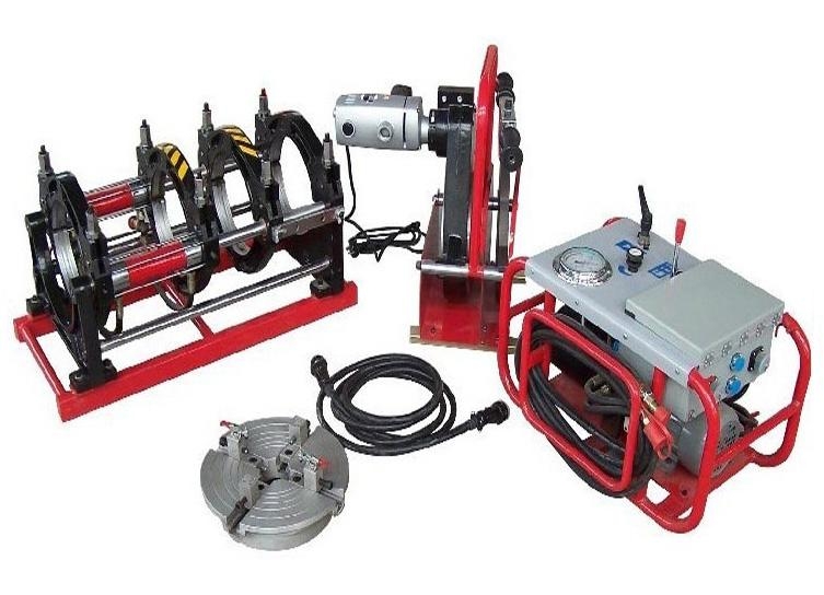
- Vernier calipers - for measuring the dimensions of the material;
- Centralizer – for fixing compression of pipes in the axial direction;\
- Trimmer - for mechanical processing;
- Hydraulic drive – for constant pressure on pipes with precise adjustment.
Butt welding polyethylene wire: procedure and action plan
- check the ovality of the polyethylene product, whether the dimensions correspond, and remove possible irregularities with an electric trimmer;
- install the pipes in the centralizer, maintaining a 4cm distance between the ends;
- This is followed by melting of the ends with a welding apparatus, and the melting process begins;
- The tube should be heated for a certain time, in accordance with which the welding table for the HDPE pipe line will help you choose.
- Immediately after heating, the HDPE is connected end-to-end using the heated ends of the pipes.
- Next, the pipe butt welding machine produces the necessary pressure, after which the final burr is created.
After the polyethylene has cooled, a collar-sealed seam is created. Distortion of the pipe wall by more than 9-10% of its thickness should not be allowed.
Polyethylene pipe welding tables
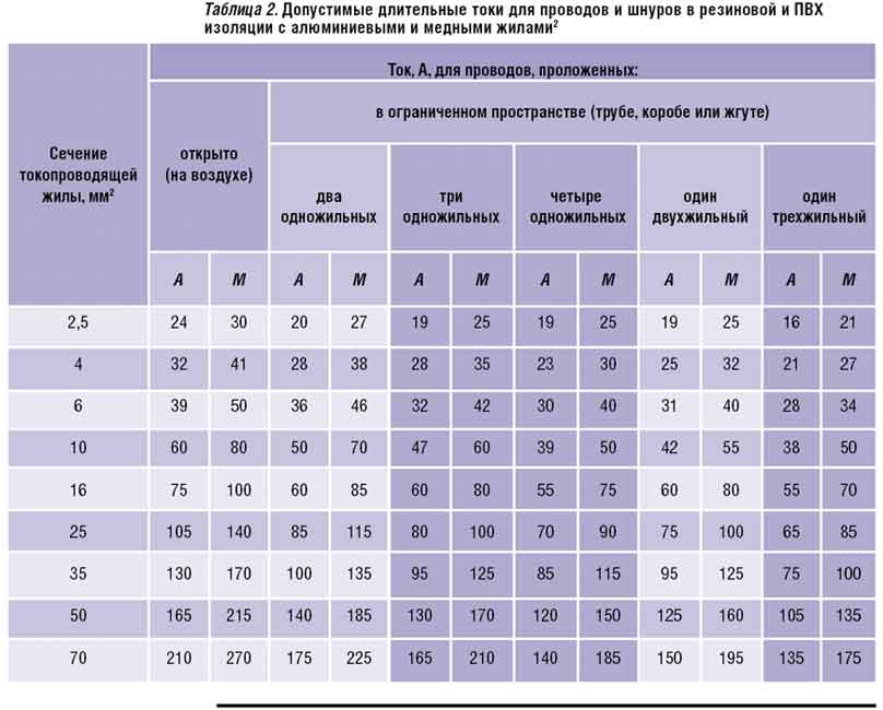
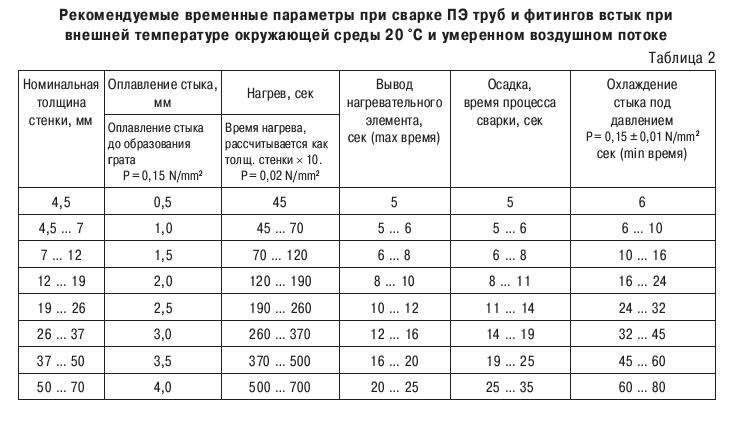 Welding time tables for HDPE pipes
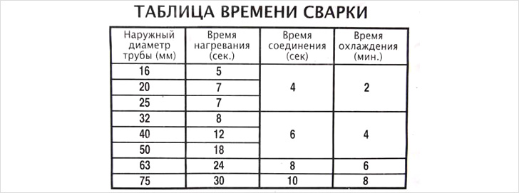
Video-Welding of polyethylene pipes
Welding of polyethylene pipes with couplings
This method is less profitable from an economic point of view, but is convenient in small spaces. Electrofusion welding of polyethylene pipes is often used during repairs; this is paramount for wires up to 150-160 mm in diameter. If you need to create an additional sleeve, this method will also be convenient. A properly created connection will withstand 14-16 atmospheres of pressure.
Welding HDPE couplings
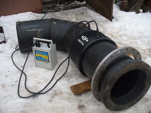 Electrofusion welding of polyester pipes
 Electric coupling is a shaped part of various sizes made of HDPE material inside which there are electrical spirals. There are different forms for different types of connections.
Creating a weld seam:
- removing contamination of pipes from grease and other unwanted substances;
- supplied to the coupling spiral electric current which increases the temperature of the ethylene and melts it.
- then the ends underneath are heated. coupling
- the pipeline expands, thereby creating the pressure necessary for welding.
- the electricity is turned off and the HDPE pipe being welded cools down, thereby forming a reliable, hermetically sealed connection. After cooling, it is removed and a document is printed - an electric welding protocol.
Video-Electrofusion welding of HDPE pipes.
Video instructions
HDPE welding: price, rent
Many companies in major cities offer a rental service for a machine for welding HDPE pipes. The user avoids the need to buy a welding machine and receive it for temporary use, saving money.
Advantages rental welding machine.
- specialist. the equipment is quite expensive, renting allows you to save;
- There is a large selection of equipment to suit your changing needs.
Price rent ranges from 2 to 4 thousand rubles per day.