The distinctive principle of the connection diagram for fluorescent lamps is the need to include starting-type devices in it, the duration of operation depends on them.
In order to understand the circuits, you need to understand the operating principle of these lamps.
The device of a fluorescent type lamp is a sealed vessel filled with a special consistency of gas. The calculation of the mixture was carried out with the aim of wasting less ionization energy of gases in comparison with conventional lamps, due to this you can save a lot on lighting a house or apartment.
For continuous illumination it is necessary to hold the glow discharge. This process is ensured by supplying the required voltage. The only problem is the following situation - such a discharge appears from a supply voltage that is higher than the operating voltage. But this problem was also solved by the manufacturers.

Electrodes are installed on both sides of the lamp, which receive voltage and maintain the discharge. Each electrode has two contacts with which the current source is connected. Due to this, the zone surrounding the electrodes is heated.
The lamp lights up after heating each electrode. This happens due to the impact of high-voltage pulses on them and subsequent voltage work.
When exposed to a discharge, the gases contained in the lamp container activate the emission of ultraviolet light, which is not perceived by the human eye. In order for human vision to distinguish this glow, the bulb inside is coated with a phosphor substance, which shifts the frequency interval of illumination into the visible interval.
By changing the structure of this substance, the range of color temperatures changes.
Important! You can’t simply plug the lamp into the network. The arc will appear after the electrodes and pulse voltage have been warmed up.
Special ballasts help ensure such conditions.
Connection diagram nuances
A circuit of this type must include a throttle and a starter.
The starter looks like a small neon light source. To power it, you need an electrical network with a variable current value, and it is also equipped with a number of bimetallic contacts.

The throttle, starter contacts and electrode threads are connected in series.
Another option is possible by replacing the starter with a button from the input bell.
The voltage will be carried out by holding the button in the pressed state. When the lamp lights up, you need to let it go.
- the connected inductor stores electromagnetic energy;
- Electricity is supplied via the starter contacts;
- current movement is carried out using tungsten filaments of heating electrodes;
- heating of electrodes and starter;
- then the starter contacts open;
- the energy that is accumulated using the throttle is released;
- the lamp turns on.

In order to increase the efficiency and reduce interference, two capacitors are introduced into the circuit model.
The advantages of this scheme:
Simplicity;
Reasonable price;
She is reliable;
Disadvantages of the scheme:
Large mass of the device;
Noisy operation;
The lamp flickers, which is not good for vision;
Consumes large number electricity;
The device turns on for about three seconds;
Poor performance at sub-zero temperatures.
Connection order
The connection using the above diagram occurs with starters. The option discussed below has a starter model S10 with a power of 4-65W, a 40W lamp and the same power for the choke.
Stage 1. Connecting the starter to the pin contacts of the lamp, which look like incandescent filaments.
Stage 2. The remaining contacts are connected to the inductor.
Stage 3. The capacitor is connected to the power pins in parallel. Due to the capacitor, the level of reactive power is compensated, and the amount of interference is reduced.
Features of the connection diagram
Thanks to the electronic ballast, the lamp provides a long period of operation and saves energy costs. When operating at voltages up to 133 kHz, light propagates without flickering.
Microcircuits provide power to the lamps and heat the electrodes, thereby increasing their productivity and extending their service life. It is possible to use dimmers in conjunction with lamps of this connection scheme - these are devices that smoothly regulate the brightness of the glow.

Electronic ballast converts the voltage. Action DC is transformed into a high-frequency and alternating current, which goes to the electrode heaters.
The frequency increases due to this, the intensity of heating of the electrodes decreases. The use of electronic ballast in the connection diagram allows you to adapt to the properties of the lamp.
Advantages of this type of scheme:
- big savings;
- the light turns on smoothly;
- no flickering;
- the lamp electrodes are warmed up carefully;
- permissible operation at low temperatures;
- compactness and low weight;
- long term validity.
Disadvantages of this type of scheme:
- complexity of the connection diagram;
- high installation requirements.
Lamp connection procedure
The lamp is connected in three stages:
The electrodes are heated, due to which the device starts up carefully and smoothly;
A powerful impulse is created, which is required for ignition;
The operating voltage is balanced and supplied to the lamp.

Connection order
Stage 1. Parallel connection of the starter to each lamp.
Stage 2. Serial connection using a choke of free contacts to the network.
Stage 3. Parallel connection of capacitors to the lamp contacts. Due to this, interference is reduced, as well as reactive power compensation.
Video - Connecting fluorescent lamps
Conventional incandescent lamps are inefficient - they produce more heat than light. And their service life is short. Connecting fluorescent lamps allows you to save almost 3 times on electricity bills. Plus, such lighting sources have a wider range of colors and are less harmful to the eyes. However, their installation requires the purchase of special devices: chokes or electronic ballast boards.
Features of fluorescent lamps
Read also:

To understand how fluorescent lamps are connected, you need to understand the principle of their operation. Outwardly, they look like glass cylinders, in which the air is completely replaced by an inert gas under slight pressure. There is also a small amount of mercury vapor that can accelerate ionization - the movement of electrons.
Electrodes are located on both sides of the cylinder. Between them there is a tungsten helix, coated with oxides of substances that, when passing current and heating, can easily move over fairly long distances, creating ultraviolet radiation(UV).

But, since this type of radiation is invisible, it is converted using a phosphor (a special composition based on calcium halophosphate, which coats the walls of the cylinder), capable of absorbing UV, in return releasing visible rays of light. The color of the lighting depends on the type of phosphor.
After turning on the device and entering the operating state, the current strength in it may increase due to a drop in gas resistance. If this process is not limited, it can quickly burn.
To reduce the current, chokes (limiters) are used - helical inductors that provide additional load and can shift the phase AC and maintain the desired power for the entire switching period. Limiting devices also have another name: ballasts or ballasts (ballasts).
Read also:
More advanced types of ballast are electronic mechanisms (electronic ballasts), the principle of operation of which will be described in the next chapter. To start the discharge, a starting device called a starter is used .
The electromagnetic choke or electronic ballast should be selected depending on the number of lamps and their power. It is prohibited to connect a device intended for two lamps to one. To avoid failure of the device, you should also not connect electronic ballasts without a load, that is, a lamp.
Operating principle
Read also: Installing a gas boiler in a private house: all the necessary requirements for quickly and legally starting a heating system (Photo & Video) + Reviews

Operating principle of fluorescent lamps
Let us briefly describe the interaction diagram between the starter, ballast and lamp:
- When power is applied, the current, passing through the ballast, passes through the starter contacts along the tungsten spirals, heating them and then goes towards zero
- The starter is equipped with a pair of contacts: movable and fixed. When current flows, the movable contact (bimetallic), heating up, changes its shape and connects with the first
- In this case, the current immediately increases significantly to the limit limited by the inductor. The electrodes are heating up
- The starter plate, on the contrary, begins to cool and disconnects the contacts. At this moment, a sharp voltage surge occurs and electrons break through the gas. When mercury turns into vapor, the light source switches to operating mode
- The starter is no longer involved in the process - its contacts are open.
Basic connection steps
Read also:

Connection diagram fluorescent lamp with a throttle is quite simple:
- Including a compensating capacitor in the circuit allows you to reduce energy losses and save energy consumption. In principle, the system will work without it, but with high energy consumption
- The voltage must pass sequentially through all points, starting with the capacitor
- Next, the ballast is included in the system. To obtain an even glow, its parameters must ideally match the lamp power
- The choke is connected to the light source in series
- After it comes out of the coil, you should connect the starter terminals
- We mount a second network contact to it
Unfortunately, the starter is not a very reliable device. Plus, during operation, the lamp may flicker, negatively affecting vision. In principle, it is possible to connect without it. This part can be replaced with a spring-loaded switch button.
Installation of two lamps
Read also:

No matter how many light sources need to be included in the lighting system, they are all connected in series. To start two lamps, two starters will be required. They are connected in parallel.
So, let’s describe the process of connecting 2 fluorescent lamps at once:
- The phase must first approach the inductor input
- From there it should go to the first lamp
- Then head to the first starter
- Next, switch to the second contact pair of the same light source
- The output contact is connected to zero
- The second pipe is connected in exactly the same sequence. The first is PRA. Then contact the second light source, etc.
If you understand the principle of this circuit, you can easily connect 3 or 4 fluorescent lamps in the same way.
A pair of lamps and one choke
Read also:

Here you will need two starters, but an expensive ballast can be used just one. The connection diagram in this case will be a little more complicated:
- Connect the wire from the starter holder to one of the light source connectors
- The second wire (it will be a sub-line) should run from the second starter holder to the other end of the light source (lamp). Please note that it has two slots on both sides. Both wires should go into parallel (identical) sockets located on the same side
- We take the wire and insert it first into the free socket of the first and then the second lamp
- In the second socket we first connect the wire with the socket connected to it
- We connect the forked second end of this wire to the inductor
- It remains to connect the second light source to the next starter. Connect the wire to the free hole in the socket of the second lamp
- The last wire connects the opposite side of the second light source to the inductor
Connection without choke
Read also:Infrared ceiling heater with thermostat - modern technologies in your home (Prices) + Reviews

This method is used mainly in old lamps when the ballast fails. This can be done by using direct current, the rating of which is higher than usual. That is, the voltage at the time of start-up should be increased. The strength of this voltage is selected based on the characteristics of both the network and the light source itself.
To connect a fluorescent lamp without a choke, you need to connect a diode bridge (or a pair of diodes). The contacts are closed on both sides in pairs. There should be a plus on one side of the light source and a minus on the other.
A similar scheme can be used even with a burnt-out filament. After all, the cylinder with gas in this method will be fed due to constant voltage. Just keep in mind that this method can be used for a short period - over time, the pipe will quickly darken, and then, due to burnout of the phosphor, it will stop emitting light altogether.
Electronic ballast connection
Read also:
Chokes are quite noisy devices. Therefore they recent years They are rarely connected to a fluorescent lighting system, replacing them with electronic ballasts, digital or analog.
Such devices no longer need a starter. Essentially, electronic triggers are small electronic circuit boards. They themselves are able to regulate the voltage level and provide even light, without flickering. Plus they are safer and less fire hazardous in operation and have a longer service life.
There can be many options for implementing electronic ballasts, but there are two main launch methods:
- the sources are preheated; this helps increase the efficiency of the device and reduce its flicker
- using an oscillatory circuit; the filament in this case is part of it; when a discharge passes, the circuit parameters change, as a result the voltage drops to the required level
You can get rid of annoying humming and blinking by replacing the old throttle with a modern electronic ballast. To do this you should:
- Disassemble the old circuit, removing the inductor, starter, and condensates from it. Only the light source and wires should remain inside
- We attach electronic ballasts selected for power to the body with self-tapping screws. If there are two lamps, then the power of the electronic mechanism should be 2 times higher
- We connect it with wires to the lamp sockets
- If assembly is done correctly, both light sources should light up simultaneously with an even, bright light. Naturally, there should be no more buzzing.
To connect fluorescent lighting devices, a fundamentally different circuit is used than that used for standard incandescent lamps. To ignite such a light source, a special starting device is installed in the circuit, the quality of which directly affects the service life of the lamp. To fully understand the features, connection diagrams, and fluorescent lamps, you need to understand the features of their design and the operating principle of such a device.
Fluorescent lamp operation
A fluorescent lighting lamp is a device consisting of a glass bulb containing special gases. The mixture inside the lamp is selected so that ionization occurs at minimum quantity energy consumption in contrast to a standard incandescent lamp, which allows you to save electricity.
To maintain the continuous glow of a fluorescent lighting device, it requires the constant presence of a glow discharge. This is achieved by applying a certain voltage level to the electrodes fluorescent lamp. The only problem in this case is the need for constant voltage supply significantly exceeding the nominal values.
This problem was solved by installing electrodes on both sides of the flask. Voltage is applied to them, due to which the discharge is continuously maintained. At the same time each electrode consists of two contacts, connected to a current source, due to which the surrounding space warms up. Therefore, the lamp begins to burn with a delay due to the heating of the electrodes.
Under the influence of electrode discharges the gas begins to glow with ultraviolet light, which is not perceived by the human eye. Therefore, to develop light, the inside of the bulb is opened with a layer of phosphor, due to which the frequency ranges change in human visible spectrum.
A fluorescent lamp cannot, unlike a standard light source with an incandescent filament, be connected directly to an alternating current network. For an arc to occur, heating of the electrodes is necessary, as a result of which a impulse voltage. To provide necessary conditions To glow a fluorescent light source, special ballasts are used. Today, electromagnetic and electronic ballast are widely used.
 This connection diagram for a fluorescent lamp involves the use of a special choke and starter. In this case, the starter is nothing more than a low-power neon light source. To connect the inductor, starter contacts and electrode thread, use a sequential method.
You can replace the starter with a standard electric doorbell button. In this case, to ignite a fluorescent lamp you will need to hold the button pressed and release only after the lamp begins to emit light. The order of operation of the light source connection circuit using an electromagnetic ballast occurs according to the following principle:
- after connecting to the AC mains, the inductor accumulates an electromagnetic charge;
- electrical energy is supplied through the contact group of the starter device;
- current begins to flow to the heating threads of the electrodes made of tungsten;
- the starter and electrodes heat up;
- the starter contact group opens;
- the energy accumulated in the throttle is released;
- the voltage changes on the electrodes;
- the fluorescent lamp begins to glow.
To increase the efficiency of a fluorescent lighting device and reduce interference that may occur when the lamp lights up, capacitors are provided in the circuit. One container is mounted directly in the starter to dampen sparking and improve neon impulses. At the same time, such a connection scheme has a number of undeniable advantages:
- maximum reliability, proven by time;
- ease of assembly;
- low price.
I would also like to note the disadvantages, of which there are quite a few:
- large dimensions and weight of the lamp;
- long lamp startup;
- low efficiency of the device when operating at low temperatures;
- a fairly high level of electricity consumption;
- characteristic noise of throttles during operation;
- flickering effect, which has a detrimental effect on human vision.
 To implement the considered scheme, you will need to use the starter. To connect one lighting fixture to the network use electromagnetic ballast S10 series. This is a modern element that has a non-flammable design and makes it as safe as possible. In this case, the main tasks of the starter are the following functions:
- ensuring that the fluorescent lamp is turned on;
- breakdown of gas gaps after prolonged heating of the electrodes.
If we consider the inductor, then its purpose in the circuit is determined by the achievement of the following goals:
- limitation of current parameters in the process of closing the electrodes;
- generating a sufficient degree of voltage capable of breaking through gases;
- maintaining discharge combustion stability.
This scheme provides for connecting a fluorescent light source with a power of up to 40 W. At the same time, the power indicators of the throttle must be similar to the lamp parameters A. In turn, the starter power can vary from 4 to 65 W. To connect the light source to the AC network in accordance with the diagram, it is necessary to perform certain manipulations.
- In progress parallel connection starter to the contacts located at the output of the fluorescent lamp.
- A choke is connected to the free pair of contacts.
- A capacitor is connected in parallel to the contacts supplying power to the lamp, designed to compensate for reactive power and reduce interference in the AC network.
 The operating principle of the 2x36 electronic ballast circuit is based on increasing the frequency characteristics. Due to this change in frequency, the glow of the luminescent device becomes uniform without flickering. Thanks to modern microcircuits the starting device consumes minimal energy and has compact dimensions, while evenly heating the electrodes.
The use of an electronic ballast in the connection circuit of a fluorescent lamp allows the device to automatically adjust to the parameters of the lamp. Thanks to this electronic ballast is much more practical and efficient, as it has the following advantages:
- high efficiency;
- uniform and gradual heating of the electrodes;
- smooth start of the lamp;
- no flickering effect;
- use of the lamp even at sub-zero temperatures;
- automatic adjustment of ballast to lamp parameters;
- high reliability;
- minimum dimensions and weight of the device;
- the longest possible service life of a fluorescent lamp.
If we consider the disadvantages of electronic ballast, there are very few of them: a complex circuit and increased requirements for execution accuracy installation work, as well as requirements for the quality of the components used.
 In most cases, manufacturers of electronic ballast complete it with all the necessary wires and connectors, as well as a circuit diagram for connecting the device. In this case, such an electronic device for starting a fluorescent lamp performs three main functions:
- provides smooth heating of the electrodes, which increases the service life of the lamp;
- creates a powerful impulse necessary to ignite the lamp;
- stabilizes the parameters of the operating voltage supplied to the lighting device.
Modern connection schemes for fluorescent light sources do not provide for the additional use of a starter. This allows you to protect the electronic ballast if the light is turned on without a lamp.
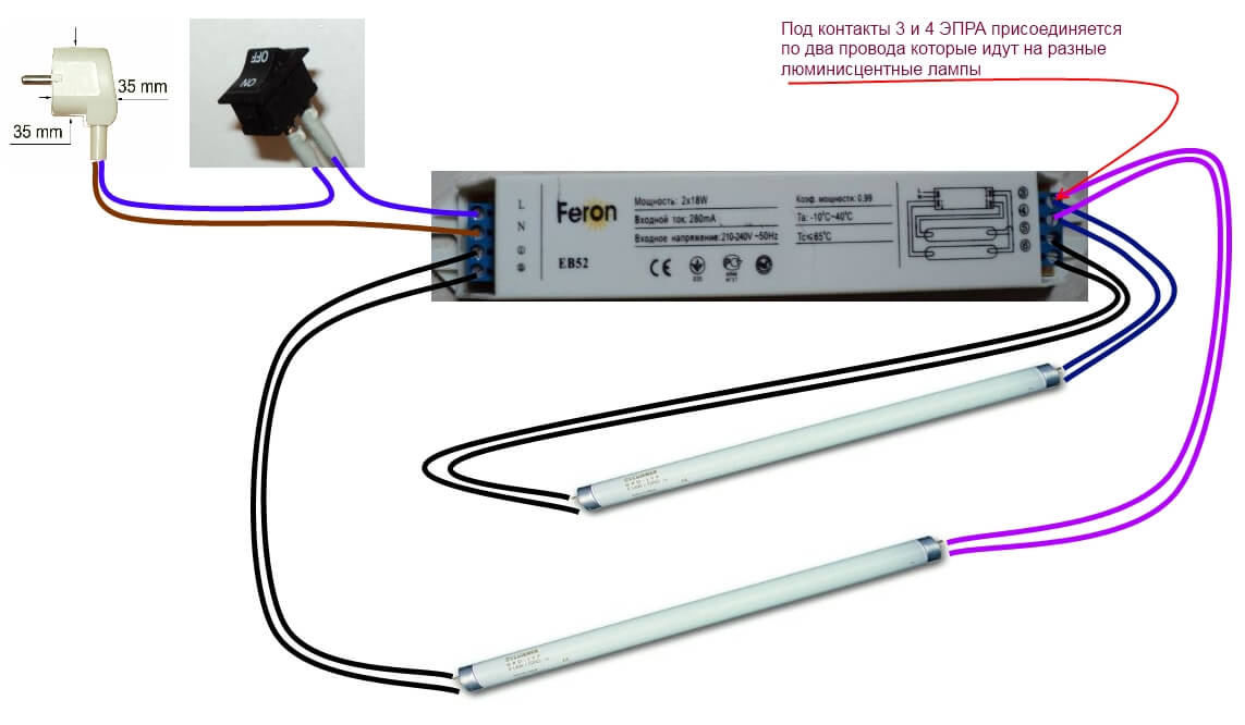
Special attention should be paid to the scheme for connecting two light sources to one ballast. At the same time serial connection of lighting devices is used, for which you will need the following components:
- induction choke;
- 2 starters;
- lighting fixtures.
The connection itself requires a certain sequence.
- A starter is installed on each lamp using a parallel connection circuit.
- Unused contacts are connected to the AC network through a choke in a serial connection method.
- In parallel to contact groups capacitors are connected to lamps.
Having familiarized yourself with the various connection diagrams for fluorescent lamps, anyone can install their own lighting fixtures in your apartment or replace them if the latter fail.
(or as we are used to calling them Fluorescent lamp) are ignited by a discharge created inside the flask.
If anyone is interested in learning about the structure of such a lamp - about their advantages and disadvantages, then you can look into.
In order to obtain a high-voltage discharge, special devices are used - ballast chokes controlled by a starter.
It works something like this: inside the lamp fittings there is a choke and a capacitor that form an oscillating circuit. A starter neon lamp with a small capacitor is installed in series with this circuit. When current passes through a neon lamp, an electrical breakdown occurs in it, the resistance of the lamp drops almost to zero, but it almost immediately begins to discharge through the capacitor. Thus, the starter opens and closes chaotically and chaotic oscillations occur in the throttle.
Due to the EMF of self-induction, these oscillations can have an amplitude of up to 1000 Volts, and they serve as a source of high-voltage pulses that light the lamp.
This design has been used in everyday life for many years and has a number of disadvantages - indefinite switching time, wear of lamp filaments and a huge level of radio interference.
As practice shows, in starter devices (a simplified diagram of one of them is shown in Fig. 1), the sections of the filaments to which the mains voltage is supplied are subject to the greatest heating. This is where the thread often burns out.

More promising - without starter ignition devices, where the filaments are not used for their intended purpose, but act as electrodes of a gas-discharge lamp - they are supplied with the voltage necessary to ignite the gas in the lamp.

Here, for example, is a device designed to power a lamp with a power of up to 40 W (Fig. 2). It works like this. The mains voltage is supplied through inductor L1 to the bridge rectifier VD3. During one of the half-cycles of the mains voltage, capacitor C2 is charged through the zener diode VD1, and capacitor S3 is charged through the zener diode VD2. During the next half-cycle, the mains voltage is summed with the voltage on these capacitors, as a result of which the EL1 lamp lights up. After this, these capacitors are quickly discharged through the zener diodes and diodes of the bridge and subsequently do not affect the operation of the device, since they are not able to charge - after all, the amplitude voltage of the network is less than the total stabilization voltage of the zener diodes and the voltage drop across the lamp.
Resistor R1 removes the residual voltage on the lamp electrodes after turning off the device, which is necessary for safe replacement of the lamp. Capacitor C1 compensates for reactive power.

In this and subsequent devices, pairs of contacts of the connector of each filament can be connected together and connected to “their” circuit - then even a lamp with burnt-out filaments will work in the lamp.
A diagram of another version of the device, designed to power a fluorescent lamp with a power of more than 40 W, is shown in Fig. 3. Here the bridge rectifier is made using diodes VD1-VD4. And the “starting” capacitors C2, C3 are charged through thermistors R1, R2 with a positive temperature coefficient of resistance. Moreover, in one half-cycle, capacitor C2 is charged (through thermistor R1 and diode VD3), and in the other - SZ (through thermistor R2 and diode VD4). Thermistors limit the charging current of the capacitors. Since the capacitors are connected in series, the voltage across lamp EL1 is sufficient to ignite it.
If the thermistors are in thermal contact with the bridge diodes, their resistance will increase when the diodes heat up, which will reduce the charging current.

Throttle, employee ballast resistance, is not necessary in the power devices under consideration and can be replaced with an incandescent lamp, as shown in Fig. 4. When the device is turned on, the lamp EL1 and thermistor R1 heat up. The alternating voltage at the input of the diode bridge VD3 increases. Capacitors C1 and C2 are charged through resistors R2, R3. When the total voltage across them reaches the ignition voltage of lamp EL2, fast discharge capacitors - this is facilitated by diodes VD1, VD2.
By supplementing a conventional incandescent lamp with this device with a fluorescent lamp, you can improve general or local lighting. For a EL2 lamp with a power of 20 W, EL1 should be 75 or 100 W, but if EL2 is used with a power of 80 W, EL1 should be 200 or 250 W. In the latter option, it is permissible to remove the charge-discharge circuits from the device from resistors R2, R3 and diodes VD1, VD2.

Some best option to power a powerful fluorescent lamp - use a device with quadrupling the rectified voltage, the diagram of which is shown in Fig. 5. Some improvement of the device that increases the reliability of its operation can be considered the addition of a thermistor connected parallel to the input of the diode bridge (between points 1, 2 of node U1). It will provide a smoother increase in voltage on the parts of the rectifier-multiplier, as well as damping the oscillatory process in a system containing reactive elements (inductor and capacitors), and therefore reducing interference penetrating the network.
The devices considered use diode bridges KTs405A or KTs402A, as well as rectifier diodes KD243G-KD243Zh or others, designed for a current of up to 1 A and a reverse voltage of 400 V. Each zener diode can be replaced by several in series connected with a lower stabilization voltage. It is advisable to use a non-polar MBGCh type capacitor for shunting the network; the remaining capacitors are MBM, K42U-2, K73-16. It is recommended to bypass the capacitors with resistors with a resistance of 1 MOhm and a power of 0.5 W. The choke must correspond to the power of the fluorescent lamp used (1UBI20 - for a lamp with a power of 20 W, 1UBI40 - 40 W, 1UBI80-80W). Instead of one 40 W lamp, it is permissible to switch on two 20 W lamps in series.
Some of the assembly parts are mounted on a board made of one-sided foil fiberglass, on which areas are left for soldering the leads of the parts and connecting petals for connecting the assembly to the luminaire circuits. After installing the unit into a housing of suitable dimensions, it is filled with epoxy compound.
Svoboda Igor Nikolaevich
Reading time: 5 minutes
A A
Fluorescent lamps have long and reliably served us everywhere. They shine when we work, relax, study, shop and play sports. Few people think that lighting this lamp is not easy. This requires special assembled circuit from starting and combustion-supporting devices.
The design of the fluorescent lamp has remained virtually unchanged since its invention in the 19th century. Devices and circuits for connecting them to the network were changed and improved. Currently, electromagnetic and electronic devices for fluorescent lamps. Each of them has its own advantages and disadvantages.
A fluorescent lamp (daylight) is a sealed container filled with gas. Electrodes with tungsten filaments are soldered into it on both sides. The glow of gas under the influence of electricity allows for illumination.
In order for the gas in the flask to begin to glow, a high voltage is applied to the electrodes and maintained for a short time.
Tungsten filaments heat up the gas and it begins to glow. When the gas flares up and begins to emit light, the voltage drops and is maintained in the so-called smoldering mode.
To start and maintain the glow in fluorescent lamps, several connection schemes to the electrical network have been developed:
- Using a classic electromagnetic ballast (EMB) - one lamp and one choke.
- Two pipes and two chokes.
- Connecting two lamps from one choke.
- Electronic ballast.
- Using a voltage multiplier.
Using electromagnetic ballast (EMB)
The standard scheme using electromagnetic ballast was invented in 1934 by the Americans, and in 1938 it was already widely used in the USA. It is simple and includes, in addition to the lamp, a choke, a starter and a capacitor.
One lamp and one choke
The choke represents an inductive reactance and can accumulate self-inductive emf. The starter is a small neon light bulb with a bimetallic contact and a capacitor. The starter capacitor serves to suppress radio interference, and the parallel capacitor to the throttle serves to correct power.
After being connected to the network, the current flows through the inductor to the lamp coil, then through the starter to the second coil. The throttle starts to accumulate electric charge. According to the circuit, a weak current initially flows, limited by the resistance of the starter. The starter contacts heat up and close. The current in the circuit increases sharply, but its safe value is ensured by the inductor.
That's why the throttle is called a ballast. The high current allows the spirals to heat the gas in the flask. At this time, the starter contacts cool down and open, and current no longer flows through the starter. But the choke has managed to accumulate energy and is already transferring it to the lamp coils. She starts to glow. The throttle, having given up the accumulated charge, subsequently acts as resistance. Supports only the glow discharge, allowing the lamp to burn. The starter is already disconnected from the circuit and does not work until the next start.
The start-up process takes a split second, but can be repeated several times without being noticed.
Advantages and disadvantages
The scheme has a number of advantages:
- Cheap and available components.
- Simple enough.
- Reliable.
Compared to modern electronic ones, the throttle device has significant disadvantages:
- Overweight.
- Quite a long startup time.
- Low reliability at low temperatures.
- Higher energy consumption.
- Noisy throttle.
- Unstable light output.
Two tubes and two chokes
The use of two pairs of chokes and lamps in one lamp leads to a heavier and larger structure. Each pair has its own starter. The power of the choke and the lamp in this case is the same, the starter is used at 220 volts.
In this case, two circuits using electromagnetic ballast operate in parallel.
The advantage of this option is its reliability. The failure of one of the branches does not affect the operation of the other. The lamp will work at least at half power.
The main disadvantage is the very bulky design.
Otherwise, it has the same pros and cons as all electronic ballasts.
Turning on two lamps from one choke
The choke is the most expensive part of a fluorescent lamp. In order to save money, a circuit for connecting two lamps from one choke is sometimes used.
Two lamps from one choke can be powered in two ways:
- Consistently.
- Parallel.
Series connection of two lamps
The standard connection diagram using electromagnetic ballast is copied.
The second lamp with its starter is connected in series with the first. The lamp turns out to be cheaper. But, several design and operational problems arise.
Constructive:
- The power of the choke must correspond to the total power of the lamps.
- Starters must be of the same type, designed for reduced voltage.
Operational:
- If one of the lamps or starters fails, the entire lamp will not work.
- Troubleshooting becomes more difficult.
Design problems are easily solved. You just need to select from those available or purchase components that match the characteristics.
Expert opinion
Izosimov Vladimir Nikolaevich
Ask a question to an expertFor a circuit with a parallel connection, you should choose starters designed for an operating voltage of 110 volts or more.
In addition to reducing the cost of the design, the serial connection has the same advantages and disadvantages as the classic electronic ballast connection.
Parallel connection
It is not difficult to assemble such a circuit. The second lamp is connected in parallel and has a separate starter. With this connection, it is advisable to connect a phase-shifting capacitor to one of the lamps. This will eliminate one of the disadvantages of electronic ballast circuits - flicker. The capacitor will shift the phase of one lamp, smooth out the overall luminous flux and make it more pleasing to the eye.
Expert opinion
Izosimov Vladimir Nikolaevich
Ask a question to an expertStarters with this assembly should be installed at 220 volts.
On to the pros electromagnetic circuits, a parallel connection adds two more:
- Saving money on one throttle.
- Smoothed light output.
Electronic ballast
Electronic starting and maintaining the combustion of fluorescent lamps was developed back in the eighties and began to be used in the early nineties of the twentieth century. The use of electronic ballast has made fluorescent lighting 20% more economical.
 At the same time, all characteristics were preserved and improved luminous flux. Uniform, flicker-free lighting is stable even with network voltage fluctuations.
This was achieved thanks to the increased frequency of the current supplied to the lamps and the high efficiency of electronic devices.
Smooth start-up and soft operating mode made it possible to almost double the service life of the lamps. Additionally, it became possible to smoothly control the brightness of the lamp. The need to use starters has disappeared. Radio interference disappeared with them.
The operating principle of electronic ballast differs from electromagnetic ballast. At the same time, it performs the same functions: heating the gas, igniting and maintaining combustion. But, it makes it more accurate and softer. Various circuits use semiconductors, capacitors, resistors and a transformer.
Electronic ballasts can have different circuit designs depending on the components used. Simplified, the passage of current through the circuit can be described by the following algorithm:
- Voltage is supplied to the rectifier.
- The rectified current is processed by an electronic converter, using a microcircuit or self-oscillator.
- Next, the voltage is regulated by thyristor switches.
- Subsequently, one channel is filtered by a choke, the other by a capacitor.
- And through two wires the voltage is supplied to a pair of lamp contacts.
- The other pair of lamp contacts is closed through a capacitor.
Favorable difference electronic systems is that the voltage supplied to the contacts of the lamps has a higher frequency than that of electromagnetic ones. It varies from 25 to 140 kHz. That is why in electronic ballast systems the flickering of lamps is minimized and their light is less tiring for the human eye.
Most manufacturers indicate connection diagrams for lamps to electronic ballasts and their power on the top side of the device. Therefore, consumers have a clear example of how to properly assemble and connect the device to the network.
IN electronic ballasts There are different numbers of connected lamps of different power, for example:
- Philips HF-P series chokes can connect from 1 to 4 tubes with a power of 14 to 40 W.
- Helvar EL series chokes are designed for one to four lamps with a power from 14 to 58 W.
- QUICKTRONIC trademark Osram type QTP5 also have the ability to control one to four lamps with a power of 14 - 58 W.
Electronic devices have a lot of advantages, of which the following can be highlighted:
- light weight and small size of the device;
- fast and fluorescent lamp-saving, smooth switching on;
- there is no flicker of light visible to the eye;
- high power factor, approximately 0.95;
- the device does not heat up;
- energy savings of 20%;
- high level fire safety and absence of risks in the work process;
- long service life of luminescent lamps;
- no high requirements for ambient temperature;
- ability to automatically adjust to flask parameters;
- absence of noise during operation;
- opportunity smooth adjustment luminous flux.
Noted by many, the only disadvantage of electronic systems is their price. But it is justified by its merits.