Design. The dimensions of the stove in plan are 51x89 cm, height 238 cm. Any fuel can be burned in it. The firebox is located in the lower part of the stove; its walls are also the walls of the stove itself, which provides bottom heating. Flue gases enter the vertical channel, reflected from the ceiling.
Material. To lay the furnace you need: brick - 355 pieces, including fireproof 110 pieces.
Laying the stove in rows. 1st row - in the front part, the bricks are laid out with butts, the corner bricks are chopped off to 3/4 of the brick, and the upper edges of the 2 middle ones are cut off, forming a slope inside the masonry to the bottom of the ash pit. The slope is shown in the section along A-A. In the rear part of the row, the space between the outer wall of the furnace and the rear wall of the ash pit is filled with dry sand. Backfilling is carried out up to the 3rd row inclusive.
Rice. 1. Heating rectangular stove 1 – ash pan; 2 – blower door; 3 – combustion door; 4 – cleaning; 5 – ceiling; 6 – chimneys; 7 – heat channel; 8-fuel tank; 9 – grate; 10 – under
2nd row - a blower door is placed in the center of the front wall. Corner bricks to the right and left of it are up to 3/4 bricks, the rest of the masonry is made of full-size bricks.
3rd row - after laying the bricks of this row, a steel strip 35 cm long and 4 cm wide is placed above the front of the ash pan, which serves as a support for the bricks that cover part of the ash pan on the next row.
Rice. 1. Laying a rectangular heating stove
4th row - cover the front part of the ash pan.
In the back part of the row, the sand backfill is laid with bricks.
Rice. 2. Laying a rectangular heating stove
5th row - a grate is placed on the hole above the ash pan. Bricks hewn at the back and front form slopes for rolling coals onto the grate.
6th row - a fire door is placed in the center of the front wall. The bricks of the rear wall are hewn with a slope inward and form one inclined plane with the bricks of the previous row. 7th - 12th row - laying the firebox. 13th row - laying outlets to cover the firebox. The front part of the side walls is laid out from 3/4 bricks.
14th - 15th row - overlap above the firebox. A hole is left in the rear part connecting the firebox with the vertical channel - hailo. 16th row - they install a cleaning door, block it from behind with a “half” laid on the edge. The shelf behind the door is covered with a layer of clay-cement mortar to completely isolate the firebox from the smoke channels located above. 17th - 20th row - laying vertical smoke channels.
21st - 22nd row - connect the lifting smoke channel coming from the firebox with the lowering channel. Here, gases from the firebox pass through the cut separating the channels into the middle lower channel, along which they reach the 18th row, and through the undercut they enter the front lift channel. 23rd - 24th row - overlap the middle and rear channels.
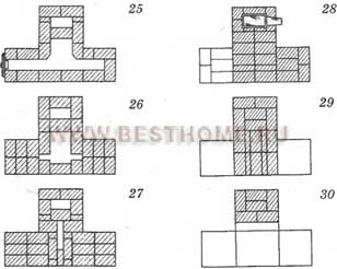
25th - 26th row - place a cleaning door at the base of the chimney, as a result, a tuck is formed from the middle channel of the second tier to the chimney. 27th - 30th row - laying the smoke channels of the second tier, of which the rear one is the beginning of the chimney.
On the 28th row the first view gate is installed. On the 30th row, the second cycle of revolutions is completed. Here, the flue gases from the front lifting channel pass into the middle lower channel and, having descended along it to the underside, on the 26th row they enter the chimney.
31st row - install outlets to cover the furnace. Rows 32 - 34 - furnace roof. The bricks are laid so that all vertical seams of the first row of the roof are covered.
On the 32nd row a 2nd view gate is installed. Installation of 2 view valves reduces heat loss from the furnace. If there are no valves, a round view is installed on the 32nd row. Row 35 and subsequent ones - laying the chimney.
Heating rectangular stove
Figure 36 (end). Laying a T-shaped furnace
5th row - laying the grate.
6th - 9th row - a firebox is laid out in the front part.
On the 8th and 9th rows, the firebox is connected to the fire chamber.
10th row - place the ceiling over the fire door.
11th - 13th row - a device for shutting off the firebox at the outlets, in the rear part there is a continuation of the laying of the fire chamber and lifting channels.
14th row - a cleaning door is installed on the facade side, an upper chamber is formed in the front part. A support column of 1/2 brick divides it into the chamber itself, connecting channels and the base of the chimney.
16th - 17th row - the laying of the rows differs from the previous ones only in the arrangement of bricks for bandaging the vertical seams.
18th - 21st row - the base of the cut is laid through the support column between the upper chamber and the chimney.
22nd - 23rd row - cover the lower heat chamber.
24th - 25th row - vertical lifting channels are connected to the upper chamber through a horizontal channel, a cleaning door is installed to clean the horizontal channel.
26th – 29th row – installation of the furnace roof.
On the 28th row, a view valve is installed, starting from the 30th row, a chimney with an internal channel of 25x13 cm is installed.
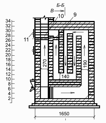
Heating rectangular stove with increased heat outputUsed for heating large rooms. The stove is simple in design; it can burn any solid fuel. The flue gases from the firebox rise through the vertical channel, but do not reach the furnace roof, but, having been reflected from the intermediate ceiling, fall to the bottom of the furnace, where through the underpass they enter the rear lifting channel, along which they rise to the furnace roof. After passing a series of revolutions, the gases go into the chimney.
To lay the furnace, 580 bricks are required.
The masonry is the same as rectangular heating stove, with the exception of the 32nd and 36th rows, where smoke dampers are installed.
MVMS furnaces with increased heatingThe frame furnace MVMS-61 is small in size, but in terms of heat transfer it is not inferior to massive furnaces. The dimensions of the stove are 40x40 cm, height 146 cm. Any solid fuel is burned in the firebox of the stove.
Flue gases from the firebox rise through the front channel until it overlaps, then through the rear channel they fall to the level of the pipe connecting the stove to the chimney.
The stove is connected to a chimney in the wall or to a main pipe.
To lay the stove, 55 bricks are required. The base of the oven is roofing steel; a layer of felt soaked in clay is laid on it. The walls and ceiling of the firebox are made of refractory bricks.
The stove frame is placed directly on the floor, strictly plumb; if the floors are wooden, asbestos or felt is laid under the stove, and a sheet of roofing iron is placed on top; The base is laid on the corners welded at the bottom of the frame, and the 1st row is laid out on it. 2nd row - lay out the space for the pull-out ash box. Subsequent masonry is carried out according to drawings and relief images.
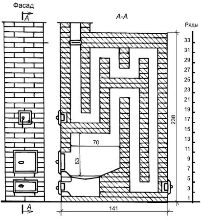
Figure 37. Heating rectangular stove with increased heat output
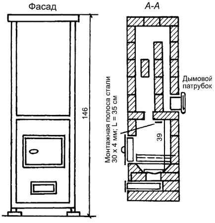
Figure 38. Furnace MVMS-61 with increased heating

Figure 38 (continued). Furnace MVMS-61 with increased heating MVMS-63 furnace for enhanced heating
The size of the stove on the plan is 52x52 cm, height 155 cm.
To lay the stove, 114 bricks are required.
The stove is connected to a chimney in the wall or to a main pipe. The installation is the same as for the MVMS-61 furnace.
Round ovens in steel casesHeating stoves, which are round in plan, are almost always enclosed in a case. Round stoves retain heat well and do not cool down even if the valve is not closed.
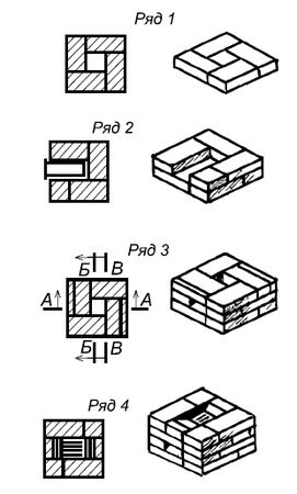
Figure 39. Laying of the MVMS-61 furnace with increased heating
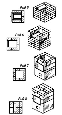
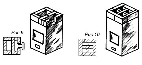

Figure 39 (continued). Masonry of the MVMS-61 furnace with increased heating
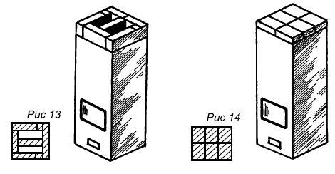
Figure 39 (end). Masonry of the MVMS-61 furnace with increased heating
Flue gases from the firebox enter the hood (chamber) through the high point in the middle of the ceiling. Part of the heat is transferred to the walls of the chamber and the ceiling of the furnace; the remaining gases, having cooled, descend through the space near the walls of the furnace into a horizontal horseshoe-shaped smoke channel connected to the chimney. 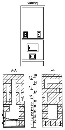
Figure 40. MVMS-63 furnace with enhanced heating
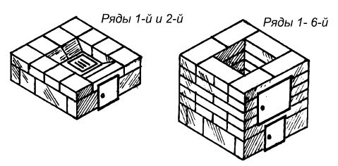
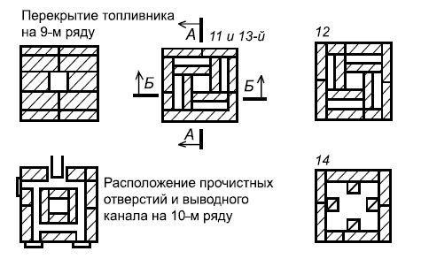
Figure 40 (continued). MVMS-63 furnace for enhanced heating
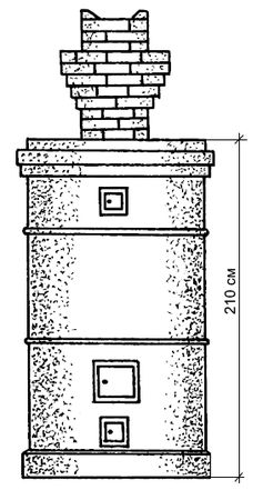
Figure 41. Construction of a round heating stove in a metal case: 1 – pass wall; 2 – base
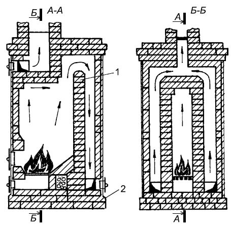
Figure 41 (end). Construction of a heating round stove in a metal case: 1 – transfer wall; 2 – base
Cold air entering the furnace through the combustion and blower doors, being heavier than that in the hood, is retained in the lower part of the furnace without cooling it.
*** To view drawings, click on the picture
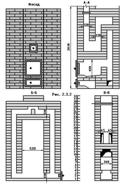
Rectangular heating stove with increased heat output. For heating large rooms it is recommended to install rectangular ovens increased heat transfer. The oven, like the one described above, is simple in design. An idea of her design features gives rice 2.3.2, which shows the facade and vertical section of the furnace.
The firebox design is the same as that of the 0-2 Giproaviaprom stove. It can burn any solid fuel. The flue gases from the firebox rise through the vertical channel, but do not reach the furnace roof, but, having been reflected from the intermediate ceiling, fall to the bottom of the furnace, where through the underpass they enter the rear lifting channel, along which they rise to the furnace roof. After then passing through a series of successive revolutions, the gases escape into the chimney. The oven has bottom heating. Due to the large area of the heated outer walls, the heat transfer of the furnace with two fireboxes per day is 6400 W.
Smoke valves are installed on the 32nd and 36th rows. The second valve is not shown in the drawing. The cross-section of the chimney channel is above the horizontal groove (13x13 cm).
For laying the stove it is required:
- Ordinary brick - 578 pcs.
- Blower door 14x25 cm - 1 pc.
- Fire door 26x27 cm - 1 pc.
- Cleaning doors 13x14 cm - 3 pcs.
- Viewing valves 25x13 cm - 2 pcs.
- Ordinary clay - 0.45 m 3
- Sand - 0.45 m 3
- Roofing felt for waterproofing - 3 m
For laying the stove it is required:
- Red brick - 490 pcs.
- Grate 25x25 cm - 1 pc.
- Fire door 28x27 cm - .1 pc.
- Blower door 14x13 cm - 1 pc.
- Cleaning door 14x13 cm - 1 pc.
- Viewing valve 25x13 cm - 1 pc.
- Furnace wire Ø2 mm. - 3 m
- Ordinary clay - 0.4 m 3
- Sand - 0.4 m3
- Pre-furnace sheet 70x50 cm - 1 pc.
- Roofing felt for waterproofing - 3 m 2
The furnace is laid in the following order (see Fig. 2.3.4 - 2.3.6).
1st row. The bottom of the ash pan is formed in the front part. The brick lying in the blower door is beveled.
2nd row. They install a blower door. A channel is formed in the rear part, which is closed on one side with a blank wall and on the other with a cleaning door.
3rd row. The bricks in the front protruding part are laid out in such a way that when laying the next row, the vertical seams are tied.
4th row. The walls of the ash chamber in this row are 18 cm thick. Increasing the thickness of the walls is necessary so that after laying the grate there are no gaps between its edges and the walls of the firebox. In the rear part, cuts begin that separate the lifting vertical channels.
5th row. Lay the grate.
6. 7, 8 and 9th rows. In the front part, a firebox with a plan size of 26x51 cm is laid out. On the 8th and 9th rows, the firebox is connected to the fire chamber.
10th row. Cover above the fire door.
11,12 and 13th rows. Firebox shut-off device at outlets. In the rear part there is a continuation of the laying of the fire chamber and lifting channels.
14th row. A cleaning door is installed on the façade side. An upper chamber is formed in the front part. Support post size. 1/2x1/2 brick divides it into the chamber itself, connecting channels and the base of the chimney.
15, 16, 17th rows. The masonry of these rows differs from the previous one only in the arrangement of bricks for bandaging the vertical seams.
18,19,20, 21st rows. The base of the cut is applied through the support column between the upper chamber and the chimney. Otherwise the masonry is the same as the previous rows.
22nd and 23rd rows. Cover the lower heating chamber.
24th and 25th rows. Vertical lifting channels are connected via a channel to the upper chamber. Install a cleaning door to clean the horizontal channel.
26, 27, 28 and 29th rows. Overlap device. On the 28th row a view gate is installed. Starting from the 30th row, lay a chimney with an internal channel of 25x13 cm.
Such stoves are still in demand today. There is an opinion that increasing the size of the furnace also leads to an increase in the heat it gives off. This is only true for heat storage. But heat transfer does not always justify fuel costs. If the fireboxes are hidden behind the smoke circulation system and they are not the outer walls of the stove, then the internal parts of the stove heat up more than the outer walls. After closing the view, heat transfer stops. The accumulated heat goes into the chimney. Small ovens with walls of 1/4, 1/2 bricks are heated with a small amount of fuel and the accumulated heat is released into the room.
The duration of the firebox is 30-40 minutes, the duration of a massive furnace is 1.5-2 hours. The longer the stove is heated, the more heat goes into the chimney.
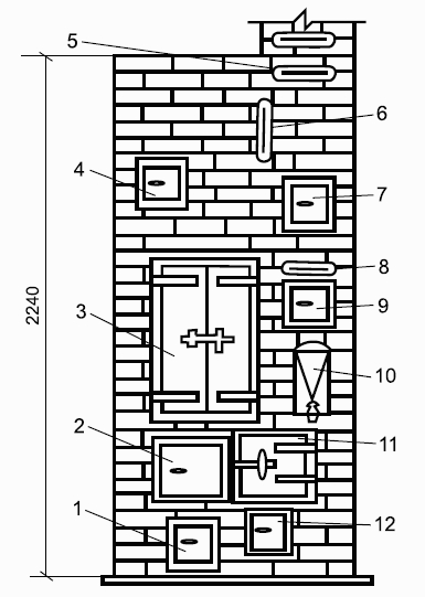
Heating rectangular stove.
The dimensions of the stove in plan are 51x89 cm, height 238 cm. Any fuel can be burned in it. The firebox is located in the lower part of the stove; its walls are also the walls of the stove itself, which provides bottom heating. Flue gases enter the vertical channel, reflected from the ceiling. To lay the furnace you need: brick - 355 pieces, including fire-resistant 110 pieces.
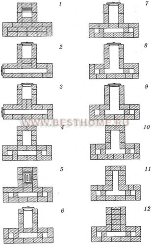
1st row - in the front part, the bricks are laid out with butts, the corner bricks are chopped off to 3/4 of the brick, and the upper edges of the two middle ones are cut off, forming a slope inside the masonry to the bottom of the ash pit. The slope is shown in the section along A-A. In the rear part of the row, the space between the outer wall of the furnace and the rear wall of the ash pit is filled with dry sand. Backfilling is carried out up to the 3rd row inclusive.
2nd row - a blower door is placed in the center of the front wall. Corner bricks to the right and left of it are up to 3/4 bricks, the rest of the masonry is made of full-size bricks.
3rd row - after laying the bricks of this row, a steel strip 35 cm long and 4 cm wide is placed above the front of the ash pan, which serves as a support for the brick that covers part of the ash pan on the next row.
4th row - cover the front part of the ash pan. In the back part of the row, the sand backfill is laid with bricks.
5th row - a grate is placed on the hole above the ash pan. Bricks hewn at the back and front form slopes for rolling coals onto the grate.
6th row - a fire door is placed in the center of the front wall. The bricks of the rear wall are hewn with a slope inward and form one inclined plane with the bricks of the previous row.
7th - 12th row - laying the firebox.
13th row - laying outlets to cover the firebox. The front part of the side walls is laid out from 3/4 bricks.
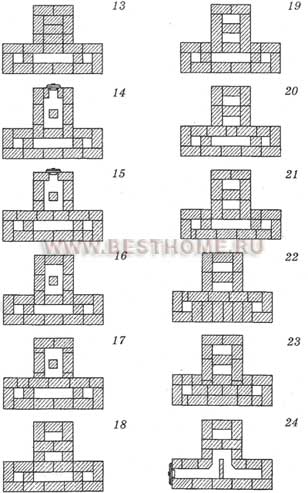
14th - 15th row - overlap above the firebox. A hole is left in the rear part connecting the firebox with the vertical channel (higho).
16th row - they install a cleaning door, block it from behind with a “half” laid on the edge. The shelf behind the door is covered with a layer of clay-cement mortar to completely isolate the firebox from the smoke channels located above.
17th - 20th row - laying vertical smoke channels.
21st - 22nd row - connect the lifting smoke channel coming from the firebox with the lowering channel. Here, gases from the firebox pass through the cut separating the channels into the middle lower channel, along which they reach the 18th row and through the undercut enter the front lift channel.
23rd - 24th row - overlap the middle and rear channels.
25th - 26th row - place a cleaning door at the base of the chimney, as a result, a tuck is formed from the middle channel of the second tier to the chimney.
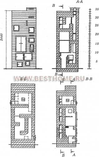
Figure 31. Heating rectangular stove.
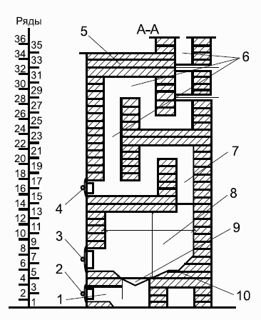
Figure 31. Heating rectangular stove (continued): 1 - ash pan; 2 - blower door; 3 - combustion door; 4 - cleaning; 5 - ceiling; 6 - chimneys; 7 - heat channel; 8 - firebox; 9 - grate; 10 - under.
27th - 30th row - laying the smoke channels of the second tier, of which the rear one is the beginning of the chimney. On the 28th row the first view gate is installed.On the 30th row, the second cycle of revolutions is completed. Here, the flue gases from the front lifting channel pass into the middle lowering channel and, having descended along it to the underside, on the 26th row they enter the chimney.31st row - install outlets to cover the furnace.Rows 32 - 34 - furnace roof. The bricks are laid so that all vertical seams of the first row of the roof are covered.On the 32nd row a 2nd view gate is installed. Installing two view valves reduces heat loss from the furnace. If there are no valves, a round view is installed on the 32nd row.
Figure 32. Laying a rectangular heating stove.
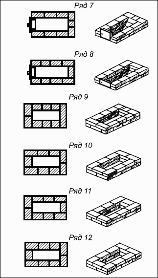

Figure 32 (continued). Laying a heating rectangular stove.
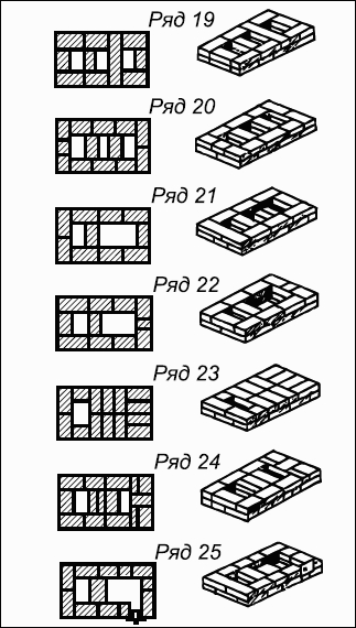
Figure 32 (continued). Laying a heating rectangular stove.
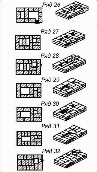
Figure 32 (continued). Laying a heating rectangular stove.
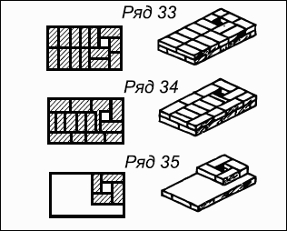
Figure 32 (end). Laying a heating rectangular stove.
Row 35 and subsequent ones - laying the chimney. Chimney laying
The pipe near the ceiling must have a groove (fluff), an expanded part that is laid out gradually.The 1st row is laid out in a “six” pattern - 6 bricks.2nd row - the brick is split into two parts along the length and laid with the unchipped parts inside. Bricks are laid flat around, increasing the dimensions by 12 cm.3rd row - laid out from two rows of bricks laid flat, the size of the masonry is increased by another 14 cm.4th row - first lay in 1/4 bricks, laying them out lengthwise, and then lay 2 rows flat around them.5th row - lay out three rows of bricks flat, increase the size of the fluff.Rows 6-8 - placed without increasing the size of the fluff. Having laid out the cutting, lay the pipe in 1/2 brick within the attic.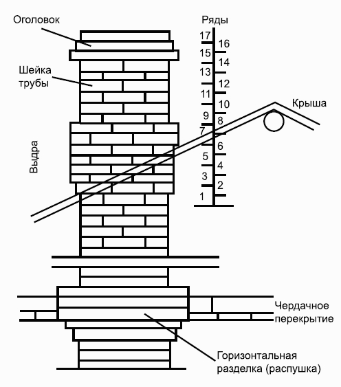
Figure 33. Chimney installationOtter masonry, neck, pipe head
Having laid out the pipe up to the roof, they put in the otter, neck, and heads.1st row - perform a “six” with 6 bricks.2nd row - from the descent side they lay 3/4 bricks, extending them 60 mm onto the pipe.3rd row - laid so that the bricks are laid flat in threes or fours with a slight extension of this part.4th row - has the same length, but the width of the masonry increases.5th-6th row - the otter clutch is expanding.The 7th row is completely exposed to the roof and expands on all sides; the brickwork is laid on edge and flat.8th row - placed in the same way, only with a different dressing of the seams. This completes the otter's laying.9th row - the laying of the neck is done in a “six” pattern, the number of rows is from the 9th to the 19th.20th row - laying the head (has 2-4 rows), the top row is mowed.
Figure 34. Chimney layingT-shaped heating stove
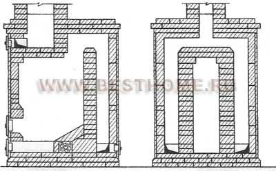
The stove is convenient for placement in partitions and is intended for heating large rooms. The firebox is used to burn any type of fuel. The walls of the firebox are the walls of the furnace. From the firebox, flue gases enter the rear chamber through the hailo.Having given off some of the heat to the walls and being reflected from the ceiling of the chamber, the gases fall down and enter the lifting channels connecting the rear chamber with the top.Having cooled, the flue gases fall into the channels connecting the upper chamber with the chimney.
Figure 35. T-shaped heating stove.
To lay the furnace, 490 bricks are required. 1st row - the bottom of the ash pit is formed in the front part, the brick lying in the blower door is beveled.2nd row - they install a blower door, a channel is formed in the rear part, which is closed on one side with a blank wall, on the other - with a cleaning door.3rd row - bricks in the front protruding part are laid out so that when laying the next row, the vertical seams are tied.4th row - the walls of the ash chamber are 18 cm thick; increasing the thickness of the walls is necessary so that after laying the grate there are no gaps between its edges and the walls of the firebox. In the rear part, cuts begin that separate the lifting vertical channels.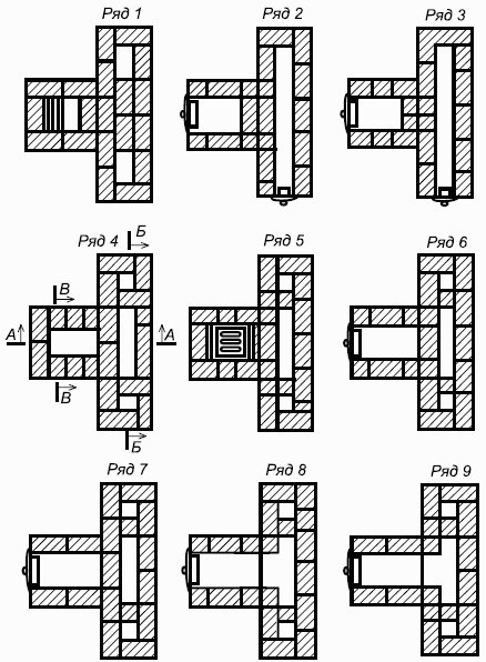
Figure 36. Laying a T-shaped furnace.

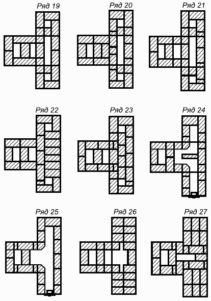
Figure 36 (continued). Laying a T-shaped stove.

Figure 36 (end). Laying a T-shaped stove.
5th row - laying the grate. 6th - 9th row - a firebox is laid out in the front part.On the 8th and 9th rows, the firebox is connected to the fire chamber.10th row - place the ceiling over the fire door.11th - 13th row - a device for shutting off the firebox at the outlets, in the rear part there is a continuation of the laying of the fire chamber and lifting channels.14th row - a cleaning door is installed on the facade side, an upper chamber is formed in the front part. A support column of 1/2 brick divides it into the chamber itself, connecting channels and the base of the chimney.16th - 17th row - the laying of the rows differs from the previous ones only in the arrangement of bricks for bandaging the vertical seams.18th - 21st row - the base of the cut is laid through the support column between the upper chamber and the chimney.22nd - 23rd row - cover the lower heat chamber.24th - 25th row - vertical lifting channels are connected to the upper chamber through a horizontal channel, a cleaning door is installed to clean the horizontal channel.26th - 29th row - installation of a furnace roof.On the 28th row, a view valve is installed, starting from the 30th row, a chimney with an internal channel of 25x13 cm is installed.Heating rectangular stove with increased heat output
Used for heating large rooms. The stove is simple in design; it can burn any solid fuel. Flue gases from the firebox rise through a vertical channel, but do not reach the furnace roof, and, having been reflected from the intermediate ceiling, descend to the bottom of the furnace, where through the underpass they enter the rear lifting channel, along which they rise to the furnace roof. After passing a series of revolutions, the gases go into the chimney.To lay the furnace, 580 bricks are required.The masonry is the same as that of a rectangular heating stove, with the exception of the 32nd and 36th rows, where smoke dampers are installed.MVMS furnaces with increased heating
The frame furnace MVMS-61 is small in size, but in terms of heat transfer it is not inferior to massive furnaces. The dimensions of the stove are 40x40 cm, height 146 cm. Any solid fuel is burned in the firebox of the stove.Flue gases from the firebox rise through the front channel until it overlaps, then through the rear channel they fall to the level of the pipe connecting the stove to the chimney.The stove is connected to a chimney in the wall or to the main pipe.To lay the stove, 55 bricks are required. The base of the oven is roofing steel; a layer of felt soaked in clay is laid on it. The walls and ceiling of the firebox are made of refractory bricks.The stove frame is placed directly on the floor, strictly plumb; if the floors are wooden, asbestos or felt is laid under the stove, and a sheet of roofing iron is placed on top; The base is laid on the corners welded at the bottom of the frame, and the 1st row is laid out on it. 2nd row - lay out the space for the pull-out ash box. Subsequent masonry is carried out according to drawings and relief images.
Figure 37. Heating rectangular stove with increased heat output.

Figure 38. Furnace MVMS-61 with increased heating.
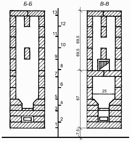
Figure 38 (continued). Furnace MVMS-61 with increased heatingMVMS-63 furnace for enhanced heating
The size of the stove on the plan is 52x52 cm, height 155 cm.To lay the stove, 114 bricks are required.The stove is connected to a chimney in the wall or to a main pipe. The installation is the same as for the MVMS-61 furnace.Round ovens in steel cases
Heating stoves, which are round in plan, are almost always enclosed in a case. Round stoves retain heat well and do not cool down even if the valve is not closed.
Figure 39. Laying of the MVMS-61 furnace with increased heating.


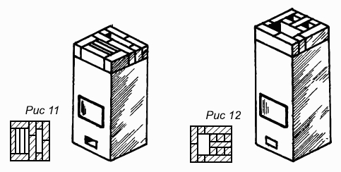
Figure 39 (continued). Masonry of the MVMS-61 furnace with increased heating.

Figure 39 (end). Masonry of the MVMS-61 furnace with increased heating.
Flue gases from the firebox enter the hood (chamber) through the high point in the middle of the ceiling. Part of the heat is transferred to the walls of the chamber and the ceiling of the furnace; the remaining gases, having cooled, descend through the space near the walls of the furnace into a horizontal horseshoe-shaped smoke channel connected to the chimney. 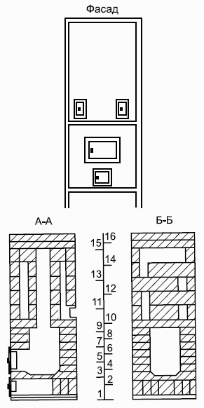
Figure 40. MVMS-63 furnace with enhanced heating.


Figure 40 (continued). MVMS-63 furnace for enhanced heating.
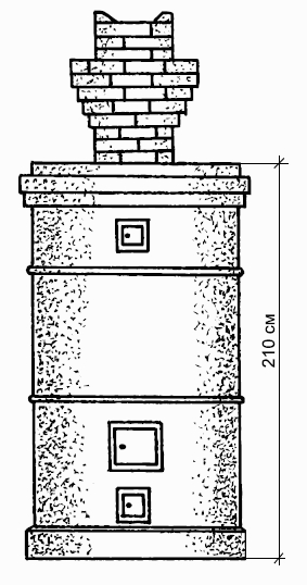
Figure 41. Construction of a round heating stove in a metal case: 1 - pass wall; 2 - base.

Figure 41 (end). Construction of a heating round stove in a metal case: 1 - transfer wall; 2 - base.
Cold air entering the furnace through the combustion and blower doors, being heavier than that in the hood, is retained in the lower part of the furnace without cooling it. Heat transfer begins soon after kindling.Heating stove, round, brick, in a metal case Oven height 229 cm, diameter 65 cm.To lay the stove you will need 260 bricks. The firebox is designed for burning any solid fuel.The stove is connected to a chimney in the wall or to a main pipe.
Figure 42. Laying a heating round stove in a metal case.
Figure 42 (continued). Laying a heating round stove in a metal case.
Figure 42 (continued). Laying a heating round stove in a metal case.
Figure 42 (continued). Laying a heating round stove in a metal case.
Figure 42 (continued). Laying a heating round stove in a metal case.
Figure 42 (continued). Laying a heating round stove in a metal case.
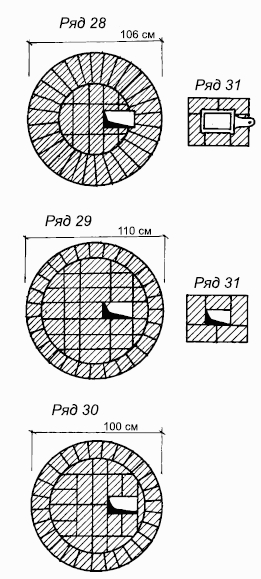
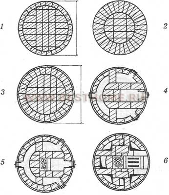
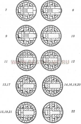
Figure 42 (continued). Laying a heating round stove in a metal caseRound stove in a metal case with helical smoke vents
The height of the stove is 209 cm, the diameter of the base is 100 cm, the diameter of the heat-emitting part is 70 cm. Heat transfer begins 20 minutes after kindling. The ash chamber is located at the base of the stove, so the stove heats up more in the lower part. Flue gases from the firebox enter the first annular channel.Making a circular path, the heat hits the walls of the furnace, heating them. Then the gases pass through the central channel into the 2nd ring channel, then into the 3rd, and from there into the chimney.To lay the stove you will need 480 bricks.Masonry features: the first 4 rows are not encased. The outermost bricks along the perimeter are cut round. It is not necessary to carefully press down the bricks. Construction of the furnace begins by determining its center on the foundation. Draw a circle with a radius of 50 cm, place the 1st row of bricks inside it.When laying the next three rows of the base, install a blower door and lay out an ash pan.A grate is placed on the 4th row. This row is laid out level, because the first casing drawer rests on it.The first drawer with the combustion door is placed on the base. If the centers of the drawer and the base coincide, then the part of the base protruding from under the drawer forms a belt 5 cm wide.The drawer is aligned with a plumb line from at least four positions after laying for stability of a row of bricks inside the drawer.The bricks are rectangular in shape, but when they are laid in a circle, voids are formed at the joints between them. They are filled with fine gravel mixed with clay mortar.The space between the brick edge and the casing is filled with clay mortar. Air pockets between the casing and the masonry reduce thermal conductivity.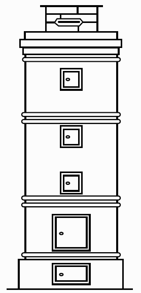
Figure 43. Round stove in a metal case with helical smoke vents.
The next casing drawer is installed when the lower drawer is lined with brick. The walls of the central channel are laid using bricks hewn onto a wedge. Rows 14, 15, 17 do not differ from 8, 9, 10, but are shifted by 135° relative to them. The cross-section of the chimney channel is 15×13 cm.Heating and cooking stoves
In addition to heating, heating and cooking stoves are designed for cooking food, baking bread, and heating water.These include: Russian oven, kitchen stove, baking oven, combined heating and cooking oven.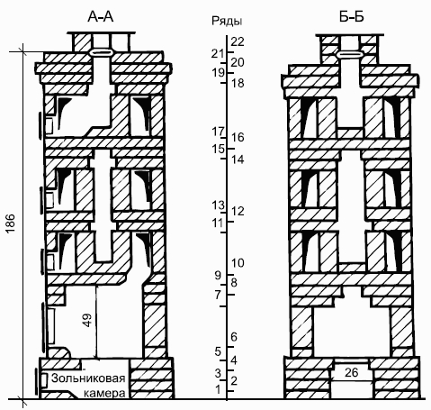
Figure 44. Construction of a round stove in a metal case with helical chimneys.
Heating parts of heating and cooking stoves come with different systems smoke circulation Large quantity heat is released into the room through the frying plate and oven, i.e. the front part of the oven has greater heat transfer than the rest.This should be taken into account when placing such stoves.Water heating boxes are placed so that heating occurs due to heat from waste gases.To prevent them from overheating, ovens are covered with a layer of clay and lined with brick walls “on edge”.Russian stove
It has an advantage over a conventional oven. In summer they are used for cooking with the release of flue gases directly into the chimney. In winter, flue gases are released directly into the shield, heating it.Oven dimensions 153x165 cm, height 238 cm.The large mass of the furnace requires an appropriate foundation of rubble stone and concrete.For ease of use, it is recommended to lay out the bricks in rows without mortar.Each row is checked for horizontalness, squareness, and verticality.Particular attention is paid to ligating the sutures, keeping the canals and the inside clean, and filling the sutures with solution. The main part of the Russian stove is the cooking chamber.The lower plane of the cooking chamber is called the hearth, the ceiling of the chamber is called the vault, the hole in the front wall through which firewood is loaded is called the mouth, the area in front of the mouth is called the hearth; At the bottom of the oven there is a baking chamber.The Russian stove does not have a grate, so coal does not burn in it. The bottom of the oven does not warm up at all right up to the hearth, so it can be cold near the floor and about front door ice even forms.
Figure 45. Laying a round stove in a metal case with screw-shaped chimneys.

Figure 45 (end). Masonry of a round stove in a metal case with screw-shaped chimneys.
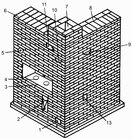
Figure 46. Russian stove: 1, 13 - cleaning; 2 - water heating box; 3 - pole; 4 - cast iron plate; 5 - samovar d=100 mm; 6 - ceiling; 7 - pipe; 8 - ceiling of the heating panel; 9, 10 - valves; 11 - view closed by a door; 12 - waterproofing (see Figure 47).
To lay a furnace, 2000 bricks are required.
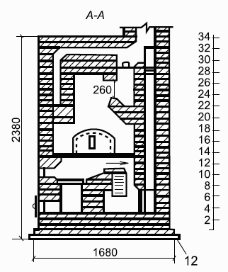
Figure 47. Construction of a Russian stove.
Features of masonry.1. Keep the channels clean from the inside.2. Completely filling the joints with mortar.3. Carefully carry out ligation of sutures.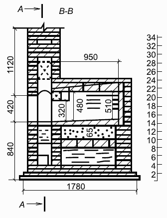
Figure 47 (continued). Construction of a Russian stove.
4. Lay out the selected bricks in order, first without mortar. 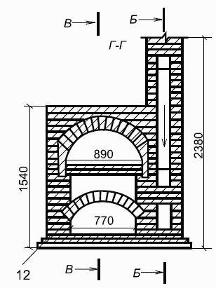
Figure 47 (continued). Construction of a Russian stove.
1st row - size 153x165, in order, the outer sides of the row are made of whole bricks, and the middle is made of halves and quarters. 2nd row - laid in the form of walls of different thicknesses with a well between them.3rd row - installation of a blower door, arrangement of an ash pan and a cleaning channel. The acute angle of the canal is beveled or secured.4th row - placed in the same way as the 3rd row.
Figure 48. Laying a Russian stove.
5th row - the blower door and cleaning are replaced with masonry. The brick laid on the side walls is cut off from the inside of the well, forming the heels needed for laying the vault.
6th row - lay out the vault with a slight rise reaching the 8th row, installing a water-heating box on the front side of the stove.
Figure 48 (continued). Laying a Russian stove.
7th row - lay out the walls and block the horizontal channel, leaving three holes: one - near the water-heating box; two - in the heating shield to form vertical channels.
Figure 48 (continued). Laying a Russian stove.
8th row - cut off the edges of the bricks laid above the ash pit.
Figure 48 (continued). Laying a Russian stove.
9th row - masonry in the same order, a firebox door is placed on the left side, as a result, a firebox of a stove and a shield is formed.
Figure 48 (continued). Laying a Russian stove.
10th row - the hot water box is covered with two bricks with hewn sides (cut B-B), cleaned and 3 channels left.
Figure 48 (continued). Laying a Russian stove.
11th row - arrange a horizontal channel, above which 3 vertical channels of the shield will be located.
Figure 48 (continued). Laying a Russian stove.
The 12th row is a solid masonry of walls and a hearth with laid cast iron plates with two burners and three channels. First, the walls of the oven are laid out, then the slabs are placed on a layer of clay. A corner is attached to the front wall, protecting this row of masonry and the laid slabs from destruction.
Figure 48 (end). Laying a Russian stove.
13th row - lay the walls of the cooking chamber 3/4 brick thick, on the outside the brick is laid flat, on the inside - on the edge. A shield and the front wall of the cooking chamber with a hole - the mouth through which fuel is loaded into the chamber - are placed in this row. 14th row - they are laid in order, and then the formwork is placed on a covered paper underneath, the formwork is needed to lay out the arch of the cooking chamber, taking into account the rise of the mouth by 480 mm, at the rear wall by 510 mm.15th row - laying a brick vault “on edge” with wrapping the brick by thickening the outer seam.The 16th - 17th row - laid out in order, in the 17th row the mouth is blocked, i.e. they close the front wall.18th row - completion of the masonry of the cooking chamber vault. They begin to lay out a stove with a width of 150 to 200 mm and a height of 210 mm. The stove is covered with the last row of masonry and a whole brick. The partitions separating the stoves must be at least 1/2 brick.19th row - masonry in order, on the left side of the stove in the over-pipe they cut a brick under a small overlap for the samovar channel. The bricks adjacent to the vault are pressed together so that they fit more tightly onto it. The opening of the overpipe is gradually shortened by laying bricks.20th - 21st row - masonry with overlap to form the bottom of the channel for the samovar.22nd row - level the top of the oven under the arch ( section B-B). From the 13th to the 28th row, all 5 channels retain their sizes.23rd row - laying in order.24th row - lengthen the overtube to the size of the 19th row, laying out the channel for the samovar.25th - 26th row - the masonry is the same as in the 24th row.27th row - overlapping the over-pipe to form a horizontal channel, installing a valve in the pipe channel, a valve in the shield channel.28th row - installation of a door and a view covering the pipe after firing the cooking chamber (sections A-A, B-B).29th row - overlapping of five vertical channels, 3 channels remain, the 2 extreme ones are long, the middle one is unchanged.Row 30 - has two long channels.31st row - forms a horizontal channel from the samovar; in order to block this channel, it is narrowed by laying the inner 1/4 of the brick.32nd row - cover all channels, excluding the pipe channel measuring 25x38 cm.33rd row - narrow this channel to a size of 25x25 cm.34th row - laying a chimney in a “six” with a channel measuring 25x25 cm.Improved Russian stove "Economka"
The oven is smaller in size, unlike the previous oven, and is simple in design. It has two fireboxes: main (large) and additional (small).Flue gases from a large firebox enter the first section of the hearth chamber, then through the underpasses into the second section, and from there through a gap in the hearth into the upper cooking chamber.
Figure 49. Improved Russian stove “Economka”.
Passing over the vault and through the hole in the front of the vault, they enter the chimney. The flue gases generated in the small firebox first enter the large firebox, and then follow the same path to the chimney. The stove is equipped with a ventilation valve and a water heating box. The operating rules are the same as for the previous oven. For masonry you will need 750 bricks. Heating and cooking oven by I. F. Volkov without a chamber for baking bread
The oven dimensions in plan are 109x89 cm, height 244 cm.For masonry you will need 520 pieces of red brick, including 100 pieces of fireproof brick. The stove has a cooking chamber, from which a fume hood, an oven, and a water heating box are made. The stove is heated in winter and summer.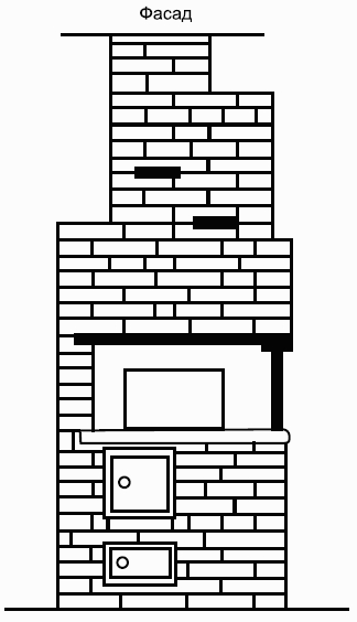
Figure 50. Improved Russian stove "Economka".
When firing in winter, the gases, having reached the water-heating box, enter in turn the 1st and then the 2nd chambers, heat them and exit through the valve into the chimney (section A-A, B-B). When burning in summer, hot gases pass under the stove, oven and hot water box, and then enter the chimney. 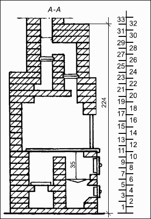
Figure 51. Construction of the “Housekeeper” stove.
First, they lay out the foundation with waterproofing, and then begin laying the furnace itself.

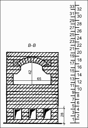
Figure 51 (continued). Construction of the "Economka" stove.

Figure 51 (end). Construction of the "Economka" stove.
1st row - solid with a recess for the ash pan. To make it easier to remove ash, the brick is pushed towards the ash pit. 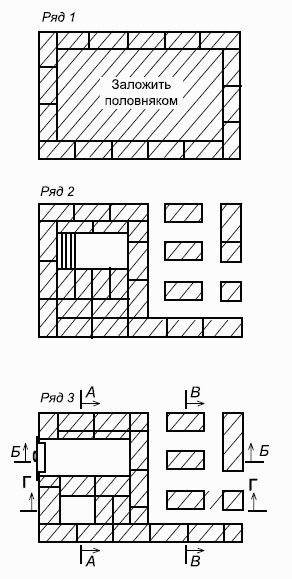
Figure 52. Laying the “Ekonomka” stove without a water-heating box.

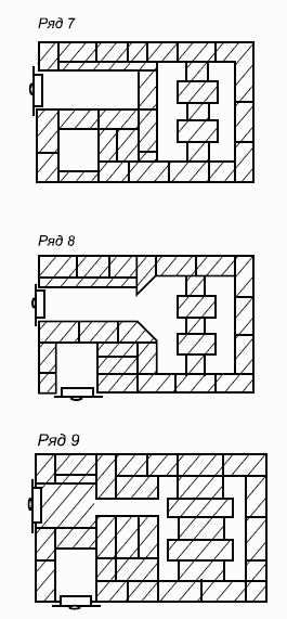
Figure 52 (continued). Laying the “Ekonomka” stove without a water-heating box.
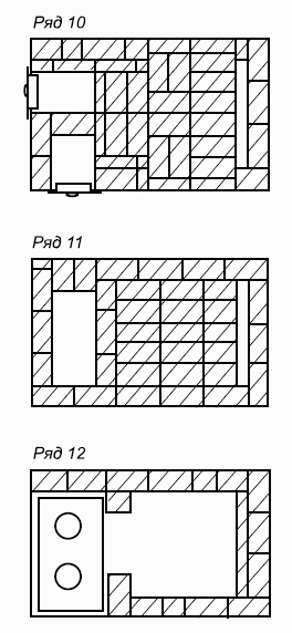
Figure 52 (continued). Laying the “Ekonomka” stove without a water-heating box.
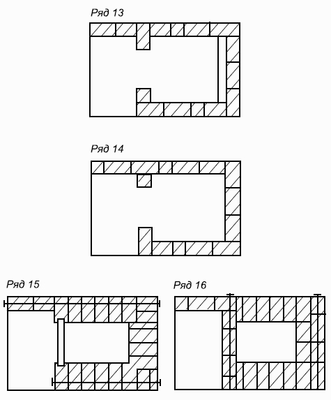
Figure 52 (continued). Laying the “Ekonomka” stove without a water-heating box.
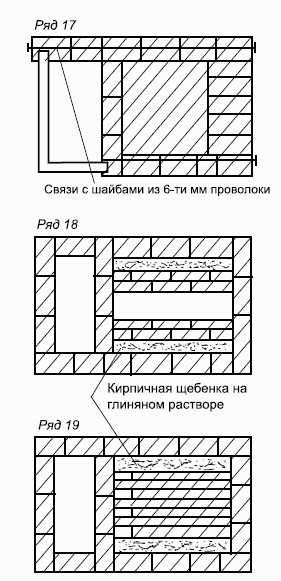
Figure 52 (continued). Laying the “Ekonomka” stove without a water-heating box.
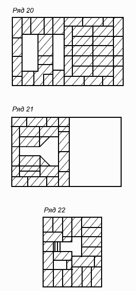
Figure 52 (continued). Laying the “Ekonomka” stove without a water-heating box.
Figure 52 (continued). Laying the “Ekonomka” stove without a water-heating box.
Figure 52 (continued). Laying the “Ekonomka” stove without a water-heating box.

Figure 52 (continued). Laying the “Ekonomka” stove without a water-heating box.
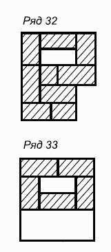
Figure 52 (end). Laying the “Ekonomka” stove without a water-heating box.
2nd row - placed as shown in the figure, with the ash pan door installed. 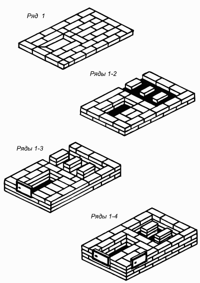
Figure 53. Laying the “Ekonomka” stove with a water-heating box
Figure 53 (continued). Laying the “Ekonomka” stove with a water-heating box.
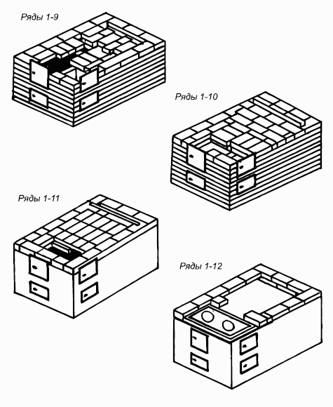
Figure 53 (end). Laying the “Ekonomka” stove with a water-heating box.
In Fig. 54: 1 - blower; 2 - firebox; 3 - cooking chamber; 4, 9, 12 - cleaning; 5 - smoke valve closing the furnace after combustion; 6 - valve opened in winter; 7 - samovar; 8 - valve opened in summer; 10 - water heating box; 11 - oven; 13 - metal mesh framed; 14 - waterproofing; 15 - closed chamber; 16 - channel for chamber ventilation; 17 - cast iron plates.
3rd row - from right side install the cleaning door. 4th row - placed with the installation of a cleaning door on the other side of the oven and an ash chamber arrangement.5th row - cover one cleaning and place a grate in it.6th row - install the furnace door and oven.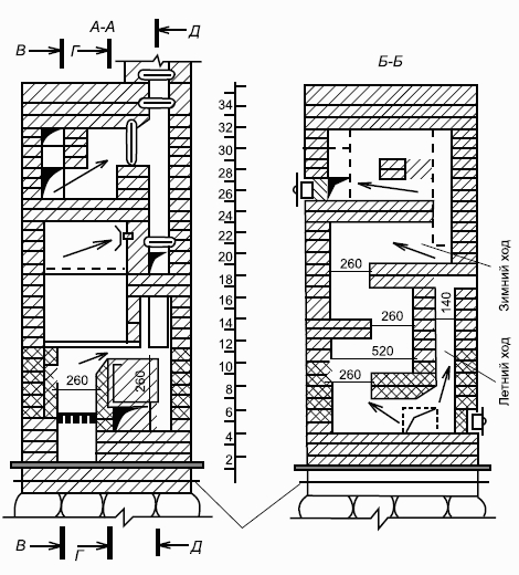
Figure 55. The design of I. F. Volkov’s heating and cooking oven without a chamber for baking bread.

Figure 55 (continued). The design of I. F. Volkov’s heating and cooking oven without a chamber for baking bread.
The 6th - 7th row overlap the long channel, forming a shorter one. 9th row - squeezed top part walls oven and change the location of the channels. 10th row - grease the top of the oven with clay.
Heating stoves serve only to heat the room. Based on the thickness of the wall masonry, heating stoves (as, indeed, all others) are divided into thick-walled and thin-walled. Thick-walled stoves are stoves whose wall thickness is greater than or equal to half a brick, thin-walled - up to a quarter of a brick.
Rice. 104.
Thick-walled stoves are very common because they have great storage capacity. But in order for the stove to work efficiently, that is, to release all the accumulated heat into the room, it is necessary to properly arrange the smoke circulation system. The walls of the firebox must be the outer walls of the furnace. A thick-walled stove needs to be heated for 1.5-2 hours.
The rectangular heating stove is simple in design and has bottom heating. The costs of its construction are relatively low. The stove has dimensions of 51 x 89 x 238 cm. Any type of solid fuel is suitable for its combustion. Its heat output is 2.4 kW (Fig. 104).
Materials. For laying a rectangular heating stove, the following materials are needed: brick - 355 pieces, including fireproof - 110 pieces; grate - 25x25 cm - 1 piece; blower door 13x14 cm - 1 piece; combustion door 25 x 20.5 cm - 1 piece; cleaning doors 13 x 14 cm - 2 pieces; view latches 13 x 13 cm - 2 pieces; ordinary clay - 0.2 m3; sand - 0.2 m3; fireclay clay - 11 kg; roofing felt or roofing felt for waterproofing - 1 sheet; pre-furnace steel sheet 50 x 70 cm - 1 piece.
Order. The first row of the stove is counted from the level of the finished floor. 1st row: corner bricks are chopped to 3/4, the front wall is laid out with pokes. Two middle bricks are cut along the upper edges, making a slope inside the masonry to the bottom of the ash pit (see section A-A). In the rear part, the space between the rear wall of the ash pit and the outer wall of the furnace is filled with dry sand up to the 3rd row inclusive. 2nd row: a blower door is installed in the center of the front wall, three-quarters are placed on either side of it; the rest of the bricks are full-sized. 3rd row: building up the masonry. When all the bricks are laid, a 4 x 35 cm steel strip is placed above the front of the ash pit, on which the ash chamber overlap is placed in the next row. 4th row: cover the ash pan. In the back part, the sand backfill is laid with bricks. 5th row: a grate is placed above the ash pan. Hewn bricks are placed in front and behind it to form a slope for rolling coals onto the grate. 6th row: a fire door is installed in the center of the front wall. The bricks of the rear wall are hewn so that their slopes are in the same inclined plane with the slopes of the bricks of the previous row. Rows 7-12: lay out the firebox. The masonry is carried out in half a brick with bandaged seams. 13th row: the front wall and part of the side walls are laid out in three-quarters - releases are made to cover the firebox. 14th and 15th rows: make an overlap over the firebox. A hole is left in the back - hailo. It serves to connect the firebox to the vertical channel. 16th row: install the cleaning door. On the right side, the door is supported with half a brick placed on its edge. The shelf behind it is covered with clay-cement mortar in order to completely isolate the firebox from the smoke channels above. 17-20th rows: laying vertical smoke channels. 21st and 22nd rows: connection of the lifting and lowering channel. At this point, the cut ends, separating the rear lifting channel coming from the firebox and the middle lowering channel. 23rd and 24th rows: overlap of the rear and middle channels. 25th and 26th rows: install a cleaning door and make a twist from the middle channel of the second tier to the chimney. 27-30th rows: laying out the smoke channels of the second tier. On the 28th row, a view gate is installed. 31st row: make outlets to cover the furnace. Rows 32-34: cover the stove with ligation of the seams. On the 32nd row a second view gate or round view is installed. This is done to reduce heat loss from the furnace. 35th row and further: laying the chimney. The cross-section of the chimney is 13 x 13 cm.
Serves for heating large rooms with a heat output of 6.3 kW. Its design is similar to that of the previous furnace. Has bottom heating, suitable for all types of fuel. The laying is carried out in the same way as the laying of a rectangular heating stove, except for the 32nd and 36th rows. View valves are placed on them.

Rice. 105.
Materials. Ordinary brick - 578 pieces; ordinary clay - 0.45 m3; sand - 0.45 m3; roofing felt or roofing felt for waterproofing - 3 m2; pre-furnace sheet 70 x 50 cm - 1 piece; grate 25 x 25 cm - 1 piece; blower door 14 x 25 cm - 1 piece; fire door 26 x 27 cm - 1 piece; cleaning doors 13 x 14 cm - 3 pieces; view latches 25 x 13 cm - 2 pieces (Fig. 105).
T-shaped heating stove
This stove can heat large rooms. It is convenient to install it in partitions. The heat output of this furnace is 5.3 kW. After laying, the stove is plastered.
Rice. 106.
Materials. Red brick - 490 pieces; ordinary clay - 0.4 m3; sand - 0.4 m3; oven wire with a diameter of 2 mm - 3 mm; pre-furnace sheet 70 x 50 cm - 1 piece; roofing felt for waterproofing - 3 m2; grate 25 x 25 - 1 piece; combustion door 28 x 27 cm - 1 piece; blower door 14x13 cm - 1 piece; cleaning doors 14 x 13 cm - 3 pieces; view latch 25 x 13 cm - 1 piece (Fig. 106).
Order. 1st row: lay out the bottom of the ash pan. The brick lying behind the blower door is hewn towards the back. 2nd row: install the blower door. A channel is made in the rear with a cleaning door on one side. 3rd row: done as the second, with ligation of the seams. 4th row: the wall thickness is increased to 18 cm. In the back, they begin to lay cuts for lifting vertical channels. 5th row: lay the grate. 6-9th rows: a firebox measuring 26 x 51 cm is laid out in the front part of the stove. 8th and 9th rows: connecting the firebox to the fire chamber. 10th row: block the furnace door. Rows 11-13: make outlets to cover the firebox and continue laying the fire chamber. 14th row: a cleaning door is installed in the front wall. A half-brick column is made in the front chamber to divide it into the chamber itself, connecting channels and the base of the chimney. 15-17th rows: the same as the 14th row, with dressing of vertical seams. Rows 18-21: make the base of the cut in the upper chamber and chimney, resting on the column. 22-23rd rows: covering the lower heat chamber. 24-25th rows: connecting the vertical lifting channel with the upper chamber using a horizontal channel. On the 24th row, a cleaning door is installed to clean the horizontal channel. Rows 26-29: arrange the furnace roof. On the 28th row, a view gate is installed. Row 30: start of laying the chimney. The cross-section of the pipe channel is 13 x 25 cm.
Heating round stove in a metal case
Rice. 107.
The advantages of stoves in metal cases are that their walls are gas-tight, they heat up evenly, and they begin to release heat soon after kindling. The stoves are quite simple in design and design. The case usually consists of three drawers, which are placed one on top of the other. The heat capacity of a round stove in a metal case is 1.75 kW. Dimensions: diameter 65 cm, height 229 cm. The firebox is designed for burning any type of solid fuel (Fig. 107).
Materials. Brick - 260 pieces, including fireproof - 65 pieces; ordinary clay - 0.05 m3; fireproof clay - 11 kg, sand - 0.03 m3; roofing steel for the case - 6.5 m2; pre-furnace sheet 50 x 70 cm - 1 piece; roofing felt or roofing felt for insulation with a diameter of 85 cm - 2 sheets, fire door 21 x 25 cm - 1 piece, grate 18 x 25 cm - 1 piece; blower door 13 x 14 cm - 1 piece; cleaning doors 13 x 14 - 2 pieces; view latches 13x13 cm - 2 pieces.

Rice. 108.
Order. Before starting work, you need to mark and cut holes in the steel sheets for the furnace, blower, cleanout doors and view valves. Construction of the stove begins with the installation of the first casing drawer on the prepared base. The installation is checked for verticality, the seams between the base and the drawer are filled with clay mortar. Then, guided by the order plan, inside the tsargi they carry out brickwork(Fig. 108).
Frame stoves
The main advantage of frame stoves is their small size with increased heat transfer, ease of manufacture, and the absence of a foundation. The heat capacity of frame stoves is from 1.2 to 3.5 kW. They use any type of solid fuel.
The frame stove consists of grates welded from a steel angle measuring 2.5 x 2.5 x 0.3 cm. Gussets are welded to the lower horizontal frame of the frame stove, and a front angle is welded to the front frame, to which combustion and cleaning doors and other metal elements are attached ovens. Bolted connections can be used instead of welding.
At the beginning of the construction of frame furnaces, the frame is installed. A metal sheet is placed on the corners of the base, then the facing sheets of the lower level are installed and the ash pit, fuel chamber and chimneys are laid out of brick. If the stove is installed on a wooden or other combustible floor, a sheet of asbestos or felt impregnated with clay mortar is placed under its base, and a sheet of roofing steel protruding 10 cm on all sides is placed on top.
After the first section of the frame is laid out, lay out the second section using scaffolding. The masonry is carried out using clay mortar. Seam dressing is required. For sealing, the roof of the furnace is covered with clay mortar and lined with asbestos-cement sheet.
Frame stoves have a convective smoke circulation system. Flue gases rise through the ascending channel to the ceiling of the furnace, spending heat on heating the upper part of the furnace, then descend through the descending channel to the ceiling of the firebox and go through the horizontal channel into the chimney. Flue gases are discharged into a chimney or wall chimney through a metal pipe.
The firebox part can be made thin-walled due to the cladding and frame. Frame stoves can be heated with any type of solid fuel. To give the stove an aesthetic appearance, use various ways cladding of frame stoves, the simplest of which is painting.
Before painting, heat-resistant putty EP-0026 is applied to the surface of the stove, which can withstand temperatures from 150 to 200 ° C. To give the stove a smooth surface, the putty is sanded with sandpaper No. 6-8. The putty is applied in three layers. After the putty has completely dried, the surface of the oven is covered with heat-resistant enamel. The first layer primes the surface. If irregularities are found, they must be sanded. The second layer is applied to a hot oven at a temperature of 120-130° C to obtain a smooth surface. Another way exterior finishing frame stoves - pasting. First, epoxy adhesive is applied to asbestos cement sheets. Fiberglass is glued on top of it - a heat-resistant material that is highly durable and quite beautiful. appearance. You can line the stove with ceramic tiles. Ceramic tiles they are laid using heat-resistant mastics or metal supporting structures are made.
Thin-walled frame oven
A thin-walled frame oven weighing 300 kg does not have a foundation. The design of the stove does not provide for a top pipe; it must be connected to a wall chimney or root pipe. The heat output of the furnace is 1.2 kW with two fireboxes per day.
Materials. To build a furnace you will need: ordinary bricks - 64 pieces, including refractory bricks - 16 pieces; ordinary clay - 40 kg; sand - 90 kg; angle steel measuring 2.5 x 2.5 x 0.3 cm - 10 kg; strip steel 3 x 0.4 cm - 2 kg; asbestos-cement sheet 5 mm thick - 2 m2, grate 13 x 13 cm - 1 piece; fire door 25 x 20.5 cm - 1 piece; sheet steel 1 mm thick - 12 pieces; roofing steel - 7 kg; pipe with valve.
Order. First, the frame is installed. The bottom of the frame is lined with sheet steel and covered with a layer of clay mortar 1 cm thick. 1st row: the front row is laid out with three bricks in spoons towards the front sheet of asbestos-cement cladding. A half-brick is placed in the left rear corner, and a full-size interlocking brick is placed on the left side. They make continuous masonry - lining. An ash box made of sheet steel 0.8 mm thick is installed on the first row. 2nd row: six halves of bricks are laid around the perimeter of the ash box. Hewn bricks are placed in front. Install the grate. Full-size bricks are placed on the sides and behind the grate. 3rd row: laid out with refractory bricks. 4th row: hewn bricks are laid “on the bed” on the sides of the furnace door. Behind the bricks, a full-length hewn brick and two hewn halves are installed to form a firebox shaft. 5th and 6th rows: in these rows the bricks are laid on edge, the laying out of the walls of the firebox ends. A cast iron strip 12 cm wide and 38 cm long is placed on top of the bricks of the 6th row. This strip will be the support for the firebox floor bricks. 7th row: laying out the arch of the firebox. A layer of clay mortar is applied to the ceiling to seal the roof of the firebox. 8th row: the walls of the furnace are laid out with bricks on edge. In this row, the cleaning is installed and the laying of the cut begins, which forms the descending and ascending channels. Rows 9-12: formation of the furnace nozzle, which increases its storage capacity. 13th row: laying out the furnace roof with six three-quarter blocks, laid “on the bed”, resting on the middle interlocking brick of the 9th row, sealing it with clay mortar and facing.
There are several designs of frame stoves, which differ from each other in weight, height, heat transfer, and size of the firebox.
"Swede" This is one of the most convenient heating and cooking stoves, since it has bottom heating and a stove with an exhaust hood, relatively small dimensions and high heat transfer. The “Swedge”, like the Russian stove, was improved over time by stove makers and designers. Below is a description of the masonry of the Shvedka stove designed by K. Ya. Buslaev. The oven dimensions are 102 x 77 x 201 cm. Heat transfer is 3600 kcal/h.
Materials. Ordinary brick - 425 pieces; including fireproof - 43 pieces; combustion door 25 x 20.5 cm - 1 piece; grate 20 x 30 cm - 1 piece; blower door 14 x 14 cm - 1 piece; cooking chamber door 50 x 39 cm - 1 piece; oven 50 x 33 x 28 cm - 1 piece; cast iron two-burner stove 70 x 40 cm - 1 piece; smoke valve 25 x 13 cm; steam exhaust valve 13 x 13 cm - 1 piece; pre-furnace sheet 70 x 50 cm - 1 piece; steel corner 4.5 x 4.5 x 101 cm - 3 pieces; steel strip 35 x 2.5 x 0.3; 20 x 2.5 x 0.2, 101 x 5 x 0.4; 75 x 5 x 0.4 cm - 4 pieces; cast iron tiles 40 x 25 cm, 40 x 15 cm - 2 pieces.
Order. 1st row: laid out according to the drawing. You can use half bricks. 2nd row: the same as the first, with mandatory ligation of the seams. Installation of a blower door. 3rd row: secure the blower door. A cleaning window is made under the oven. 4th row: make the base for the oven. The oven is lined with refractory bricks on the side of the firebox, and reinforced with sheets of roofing iron on the other three sides. 5th row: close the blower door and the cleaning window. In the same row, a grate is placed, the base of the firebox is laid with refractory bricks, and a fire door is installed. 6th row: secure the oven and fire door. 7th row: the walls of the oven are lined with refractory bricks. The brick is placed on its edge. 8th row: laid out in order. 9th row: the oven is covered with a layer of clay mortar 0.5-1 cm thick, the fire door is covered with a steel strip. Install a cast iron stove with burners, reinforcing it with 10 mm steel plates. From the slab the masonry is laid on an edge. 10th row: begin laying the smoke circulation, leaving a window for cleaning. The stove with burners is not installed. 11th row: overlap the first cleaning and make two new ones to clean the lowering channels. Two steel strips 20-25 cm long are placed on the bricks of this row - the basis for the hanging walls. 12th row: cover the cleaning of the lower channels. At this level, a wire is attached that secures the frame of the cooking chamber door. 13th row: lay bricks on edge to create a steam hood. 14th row: cover the cooking chamber, leaving a hole for the hood. 15th and 16th rows: laid out in order, leaving space for two stoves. After laying the 16th row, the small stove is covered with a sheet of roofing steel measuring 30 x 28 cm. 17th row: laid according to the order. 18th row: a cleaning hole is made in the back wall of the large stove. The internal walls of the first and second channels do not overlap by 20 and 13 cm, respectively. The upper edges of these walls are crowded. 19th row: laying is done flat. This creates a protrusion of 3 cm. Row 20: block the chimney. In this row, another protrusion of 3 cm is formed from the outside of the oven. To cover the stove, place a corner on the edge and a steel strip in the middle. 21st row: covering the large stove and part of the chimney. The row is laid out according to the size of the 19th row. Smoke and steam valves are also installed here. 22nd row: lay out the neck of the stove in three rows, reducing the cross-section of the chimney to 13 x 26 cm in order to install the second damper. Then lay out the chimney with grooves (Fig. 109).

Rice. 109.
Heating and cooking furnace designed by I. F. Volkov
The stove has dimensions of 109 x 89 x 244 cm. Its heat output is 3.9 kW with two fireboxes per day. This oven has a cooking chamber with a fume hood, an oven and a water heating box. The stove can operate in two modes, summer and winter (Fig. 110).
Rice. 110.
Materials. To build a furnace you will need: bricks - 520 pieces, including refractory bricks - 100 pieces; clay solution - 20 buckets; refractory clay mortar - 50 kg; grate 18 x 25 cm - 1 piece; combustion door 21 x 25 cm - 1 piece; blower, cleaning doors 13 x 13 cm - 5 pieces; door for the cooking chamber with a frame 38 x 64 cm - 1 piece; cast iron stove with burner - 2 pieces; cast iron plate 18 x 53 cm - 1 piece; water heating box 15 x 28 x 57 cm - 1 piece; oven 30 x 28 x 57 cm - 1 piece; drying rack 35 x 58 - 1 piece.
Order. 1st row: laid out solid, leaving space for an ash pan measuring 25 x 13 cm. One brick is cut off, tilting towards the ash pan. 2nd row: lay out with ligation of seams, install a blower door. 3rd row: the first cleaning door is installed to the right of the blower door; the blower hole is made using hewn bricks. 4th row: a second cleaning door is installed on the right wall of the oven, the ash door is closed, and near the second cleaning door a half of a brick is placed on which the oven will rest. 5th row: the masonry is made of refractory bricks, a grate is installed above the opening of the ash pit, and the first cleaning is blocked. 6th row: install the oven and fire door. 7th row: block the channel, line the side walls of the oven with bricks. 8th row: completely block the channel behind the oven. 9th row: completion of the oven lining from the side of the firebox, the top brick is released 1-1.5 cm above the oven and trimmed off. The top of the oven is covered with clay mortar. 10th row: cover the firebox door and the partition between the oven and the oven wall. 11th row: install cast iron stoves with burners above the firebox, then a water heating box and the cooking chamber door. The distance between the water-heating box and the cooking chamber is 5-7 cm, the thickness of the brick laid on edge. 12th row: partially overlap the horizontal channel. 13th row: completely block the channel. 14th row: the horizontal channel is extended, a brick hewn back is placed behind the water-heating box. 15th row: the water heating box is covered. 16th row: move the channel above the water-heating box forward half a brick, place five pieces of strip steel 12 cm long, 2.5 cm wide and 3 mm thick on three sides of the cooking chamber, the ends should extend 2 cm into the cooking chamber. Two pieces the same steel 15 cm long is placed under the brick on the back side of the stove. 17th row: lay the drying grid and install the cleaning unit above the hot water box. 18th row: reduce the channel above the cleaning. 19th row: stop cleaning and install a summer valve. 20th row: place the hood on the right side of the cooking chamber. Angular steel is placed on the inside. 21st row: the top of the cooking chamber is covered with three strips of steel. 22nd row: cover the chamber, the hood, part of the rear channel. 23rd row: install the samovar. 24th and 25th rows: install two cleanings, begin laying the upper part of the stove. 26th row: overlap the cleaning and horizontal channel. 27th row: a vertical valve is installed. 28th and 29th rows: according to the order. 30th row: cover the top of the oven, leaving one channel. 31st row: install the last horizontal valve. This is the second row of flooring. 32nd row: third row of overlap. 33rd row and further: laying the chimney.