Figure 36 (end). Laying a T-shaped furnace
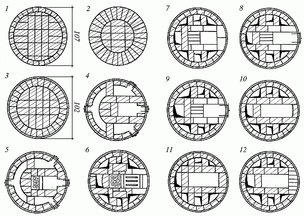
5th row - laying the grate.
6th - 9th row - a firebox is laid out in the front part.
On the 8th and 9th rows the firebox is connected to the fire chamber.
10th row - place the ceiling over the fire door.
11th - 13th row - a device for shutting off the firebox at the outlets, in the rear part there is a continuation of the laying of the fire chamber and lifting channels.
14th row - a cleaning door is installed on the facade side, an upper chamber is formed in the front part. A support column of 1/2 brick divides it into the chamber itself, connecting channels and the base of the chimney.
16th - 17th row - the laying of the rows differs from the previous ones only in the arrangement of bricks for bandaging the vertical seams.
18th - 21st row - the base of the cut is laid through the support column between the upper chamber and the chimney.
22nd - 23rd row - cover the lower heat chamber.
24th – 25th row – vertical lifting channels are connected to the upper chamber via a horizontal channel, a cleaning door is installed to clean the horizontal channel.
26th – 29th row – installation of the furnace roof.
On the 28th row, place a view valve; starting from the 30th row, place chimney with internal channel 25×13 cm.
Heating rectangular stove with increased heat outputUsed for heating large rooms. The stove is simple in design; it can burn any solid fuel. The flue gases from the firebox rise through the vertical channel, but do not reach the furnace roof, but, having been reflected from the intermediate ceiling, fall to the bottom of the furnace, where through the underpass they enter the rear lifting channel, along which they rise to the furnace roof. After passing a series of revolutions, the gases go into the chimney.
To lay the furnace, 580 bricks are required.
The masonry is the same as that of a rectangular heating stove, with the exception of the 32nd and 36th rows, where smoke dampers are installed.
MVMS furnaces with increased heatingThe frame furnace MVMS-61 is small in size, but in terms of heat transfer it is not inferior to massive furnaces. The dimensions of the stove are 40x40 cm, height 146 cm. Any solid fuel is burned in the firebox of the stove.
Flue gases from the firebox rise through the front channel until it overlaps, then through the rear channel they fall to the level of the pipe connecting the stove to the chimney.
The stove is connected to a chimney in the wall or to the main pipe.
To lay the stove, 55 bricks are required. The base of the oven is roofing steel; a layer of felt soaked in clay is laid on it. The walls and ceiling of the firebox are made of refractory bricks.
The stove frame is placed directly on the floor, strictly plumb; if the floors are wooden, asbestos or felt is laid under the stove, and a sheet of roofing iron is placed on top; The base is laid on the corners welded at the bottom of the frame, and the 1st row is laid out on it. 2nd row - lay out the space for the pull-out ash box. Subsequent masonry is carried out according to drawings and relief images.
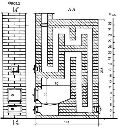
Figure 37. Heating rectangular stove with increased heat output
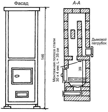
Figure 38. Furnace MVMS-61 with increased heating
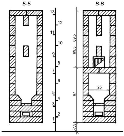
Figure 38 (continued). Furnace MVMS-61 with increased heating MVMS-63 furnace for enhanced heating
The size of the stove on the plan is 52x52 cm, height 155 cm.
To lay the furnace, 114 bricks are required.
The stove is connected to a chimney in the wall or to the main pipe. The installation is the same as for the MVMS-61 furnace.
Round ovens in steel casesHeating stoves, which are round in plan, are almost always enclosed in a case. Round stoves retain heat well and do not cool down even if the valve is not closed.
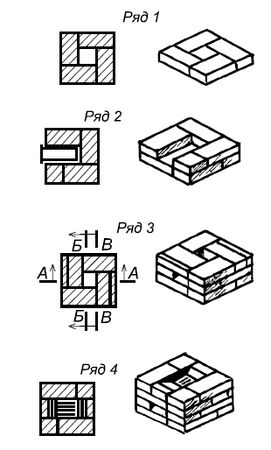
Figure 39. Laying of the MVMS-61 furnace with increased heating
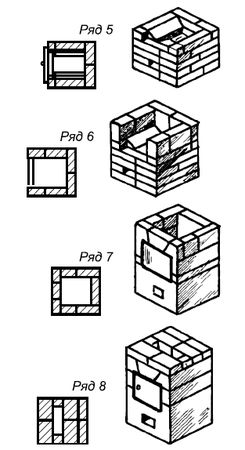
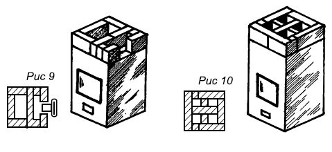
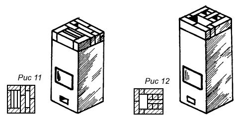
Figure 39 (continued). Masonry of the MVMS-61 furnace with increased heating
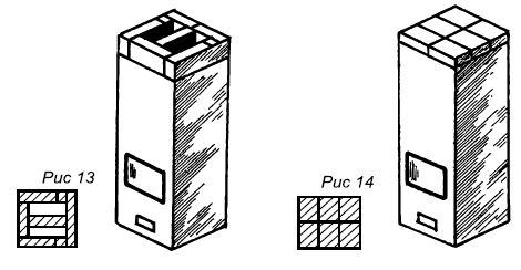
Figure 39 (end). Masonry of the MVMS-61 furnace with increased heating
Flue gases from the firebox enter the hood (chamber) through the high point in the middle of the ceiling. Part of the heat is transferred to the walls of the chamber and the ceiling of the furnace; the remaining gases, having cooled, descend through the space near the walls of the furnace into a horizontal horseshoe-shaped smoke channel connected to the chimney. 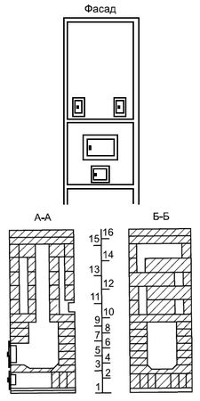
Figure 40. MVMS-63 furnace with enhanced heating
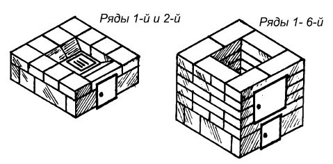
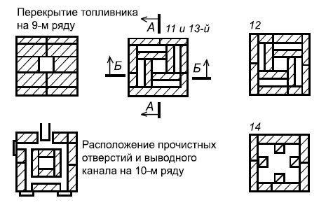
Figure 40 (continued). MVMS-63 furnace for enhanced heating
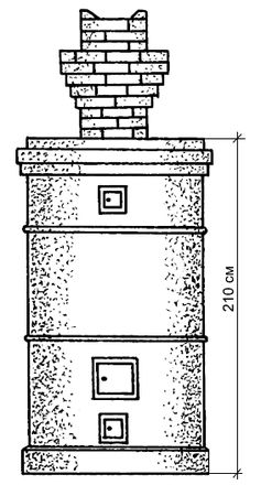
Figure 41. Construction of a round heating stove in a metal case: 1 – pass wall; 2 – base
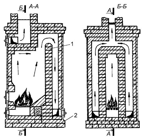
Figure 41 (end). Construction of a heating round stove in a metal case: 1 – transfer wall; 2 – base
Cold air entering the furnace through the combustion and blower doors, being heavier than that in the hood, is retained in the lower part of the furnace without cooling it.
Heating stoves
Heating stoves differ in the duration of combustion (short-term or long burning), the amount of heat transfer and the degree of heating (moderate and increased).
Moderately heated ovens, as a rule, have walls at least half a brick thick. They warm up slowly during combustion and retain heat for a long time, but also cool down slowly. With one or two fires per day, a uniform air temperature is maintained in the room. On their surface, the temperature of maximum heating is on average no more than 55-60°C, and at some points - 85-90°C. All this eliminates dust burning and improves hygienic conditions in the room. Stoves are widespread in the northern and middle zones of our country. Their service life is 30-40 years. Such furnaces have some disadvantages: large mass, requiring a solid foundation and large quantity all kinds of materials, and occupy a fairly large area.
High-heat furnaces have thinner walls, a quarter of a brick is poured. They warm up and cool down faster, the temperature on their surface averages 65-75°C, and at some points reaches 120°C. At this temperature, dust begins to burn on them, emitting an unpleasant odor. In addition, they do not maintain a uniform temperature in the room and are thus inferior to thick-walled stoves (moderate heating). Basically, in these furnaces, only the fireboxes are made with walls half a brick thick, the rest of the furnace is made of a quarter of a brick. Such ovens take up less space and require less material and resources.
Furnaces in plan form are square or rectangular, round and angular (triangular). Square and rectangular stoves are simpler to install. Round stoves, which are more attractive in appearance, are always placed in metal cases. Corner stoves are conveniently placed in the corners of the room.
According to the smoke circulation system, they are multi-turn, in which vertical and horizontal channels with a large number of turns are located sequentially. They can be single- and double-turn, with one or several lower channels located in parallel, as well as channelless or bell-type, with bottom heating and a combined smoke circulation system.
Smoke is discharged through root or manifold pipes or through wall smoke ducts.
These stoves can be brick, tiled, metal cased, smooth or corrugated sheet steel, unfinished metal frame or lined with asbestos plywood sheets, sheet steel or glazed parts. In addition to stoves made of brick, there are block stoves made of ceramics or heat-resistant concrete. These ovens are easy and quick to assemble.
Furnaces are made single-story and multi-story. Depending on the design and purpose, stoves come with a regular (periodic) combustion mode and slow or continuous combustion. In the latest furnaces, the combustion process is extended in time or occurs continuously. Because of this, the surface of the oven does not cool down.
Many of the furnaces under consideration have a thermal characteristic with two fireboxes per day for each furnace wall separately. This is done because not all of them heat up equally. In some ovens, the front and back walls heat up almost half as much as the right and left ones. It happens that the front wall heats up much more than the rest.
Plaster heating stoves after complete drying and settling of the masonry. In this case, the seams are selected to a depth of at least 1 cm. The solution is applied to the hot walls of the oven.
This section discusses the laying of the first furnace in more detail, the rest are described more briefly. Thus, the first furnace must be worked out very thoroughly.
Plastered stove with heat output 1760 kcal/h
The heating stove (Fig. 74) has dimensions: width - 510 mm, length - 770, height - 2150 mm. The front and back walls account for 340 kcal/h, the left and right walls - 540 kcal/h.
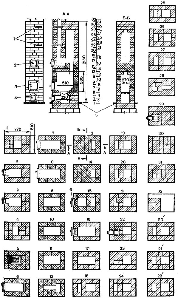
Materials: ordinary brick - 210 pieces; refractory brick - 76 pieces; ordinary clay - seven buckets; refractory clay - 23 kg; sand - 3.5 buckets; grate - 252×250 mm; combustion door - 250×205 mm; blower door - 130×140 mm; cleaning door - 130×140 mm; two smoke valves - 130×130 mm; pre-furnace sheet - 500×700 mm; 2 m of waterproofing (roofing felt) - 800×550 mm. Refractory brick, shaded with cells, can be replaced with ordinary selected brick.
The first row is made rectangular strictly in size, with a device in the middle of the masonry ash pan measuring 260x260 mm. On the left side of the order, the brick is cut off (see section A-A), which ensures easier removal of ash.
In the second row, install the blower door, resting it on the first row and carefully securing it.
The third row is similar to the second, only the order of laying the bricks is changed, which ensures that the seams are bandaged.
The fourth row covers the blower door and reduces the size of the hole above the blower to 260x200 mm, on which the grate is laid in the next row.
In the fifth row, a grate is first laid over the hole in the fourth row, then the masonry is made so that between the grate and the masonry there is a gap of at least 10 mm around the entire perimeter, necessary for the expansion of the heated metal. The brick on the side of the combustion door (on the left side) is cut off at the end so that the fuel rolls onto the grate and burns normally.
During the laying process, pay attention to the order.
The sixth row forms a firebox. The brick on the back side of the firebox is cut off. The combustion door is installed and secured on the front side.
The seventh and eighth rows are the same, except for the seam dressing. If in the sixth row the back wall of the stove (firebox) was laid out three-quarters of a brick thick, then in these rows it is laid in half a brick.
The ninth - eleventh rows are exactly the same, with the exception of dressing the seams. The ninth row covers the combustion door.
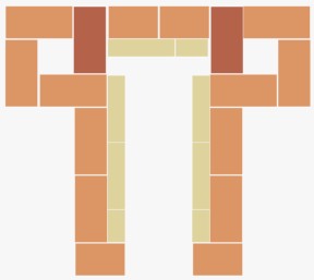
The twelfth row is laid according to the order in which eight three-fours and one half of a brick are used. This masonry narrows the firebox, which is necessary to cover it in the next row. In this order, it resembles the letter T.
The thirteenth and fourteenth rows are the same, except for the binding of the seams. With them right side only one channel remains, the rest is blocked.
In the fifteenth row, the same channel remains on the right side, and on the left, cleaning is done by installing a door in the fourteenth row opposite the pipe channel.
The sixteenth and seventeenth rows are similar, only the seventeenth row overlaps the cleaning door, leaving a rectangular horizontal channel in it.
The eighteenth - twentieth rows are laid in the same way, but with observance of ligation of the seams, dividing the large channel into two. The channel on the left side measuring 260x130 mm is directed into the pipe.
The twenty-first row is placed so that the left channel is overlapped by the three-four, reducing it by 1/4. This is necessary to further hold the brick covering half of the channel.
The twenty-second row covers half of the channel on the left side of the furnace, and a valve is installed on the remaining half.
The twenty-third row is placed in order, forming a channel measuring 130x130 mm above the valve.
From the twenty-fourth to the twenty-seventh row inclusive, the masonry is performed in the same way, only with the observance of dressing the seams.
On the left side of the furnace, the channel expands to a size of 260x130 mm. The channel on the right side, starting from the eighteenth row, remains unchanged with a size of 260x260 mm.
The twenty-eighth row is similar to the twenty-first row, only the channel on the right side is reduced to a size of 260x130 mm.
The twenty-ninth row covers the top of the furnace, and a second valve is placed on it.
The thirtieth and thirty-first rows also cover the top of the furnace, leaving the pipe channel and observing the ligation of the seams.
The thirty-second row shows the laying of a pipe in four bricks with a channel size of 130x130 mm.
If the room is 2.7 m high, then three rows should be inserted between the nineteenth and twentieth rows: 20", 21" and 22", observing the ligation of the seams.
Having folded the stove, they begin to lay the pipes, strictly observing the dressing of seams and fire safety measures when passing through the attic floor and roof.
Plastered stove with heat output 1940 kcal/h
The heating stove (Fig. 75) has dimensions: width - 510 mm, length - 890, height - 2150 mm. The front and back walls account for 335 kcal/hour, and the right and left walls account for 635 kcal/hour.
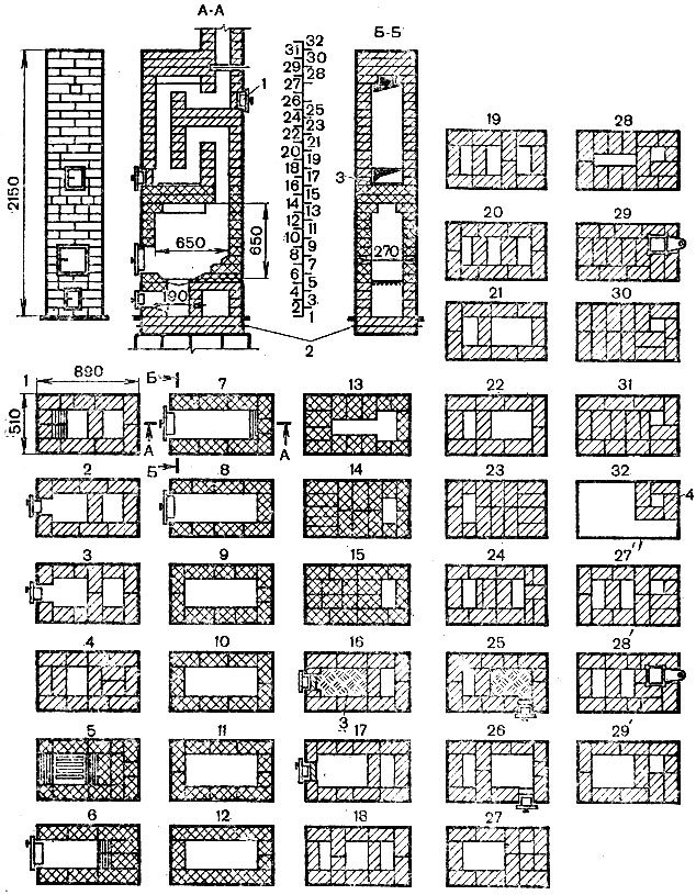
Rice. 75. Heating stove, plastered, with heat output 1940 kcal/h: 1 - cleaning; 2 - waterproofing; 3 - layer of clay-sand mortar; 4 - mounted pipe with channel 140×140 mm
Materials: ordinary brick - 245 pieces; refractory brick 110 pieces; ordinary clay - eight buckets: refractory clay - 11 kg; sand - seven buckets; grate - 252×250 mm; combustion door - 250×205 mm; blower grill - 130×140 mm; two cleaning doors - 130×140 mm; two smoke valves - 130×130 mm; pre-furnace sheet - 500×700 mm; 2 m of waterproofing (roofing felt) - 1000×1000 mm. Refractory brick is shaded with cells. It can be replaced with selected ordinary bricks. Since the previous oven was described in detail, this one, which is in many ways similar to it, will be discussed more briefly.
The first, fifth, sixth and seventh rows shaded in the figure show that the brick inside the channels and on both sides of the grate is cut off (section A-A). The thirteenth row overlaps the previously made firebox in the form of a rectangle so that a channel in the form remains above it letter T. Subsequently, it is narrowed and reduced to a size of 130 × 260 mm. In the sixteenth and twenty-fifth rows, the brick planes are leveled by laying 10 mm of clay-sand mortar on them, thereby making them smoother, which makes it easier to remove soot.
The pipe channel is laid in four bricks measuring 130x130 or 140x140 mm, which depends on the thickness of the seams. The firebox is designed for firewood. In rooms with a height of 2.7 m, rows 27", 28" and 29" are inserted between the twenty-sixth and twenty-seventh rows.
The design of this furnace was proposed by V.I. Strezhnev.
Plastered stove with heat output 2400 kcal/h
The heating stove (Fig. 76) has dimensions: width - 510 mm, length - 1400, height - 2150 mm. The front and back walls account for 280 kcal/hour, and the right and left walls account for 920 kcal/hour.
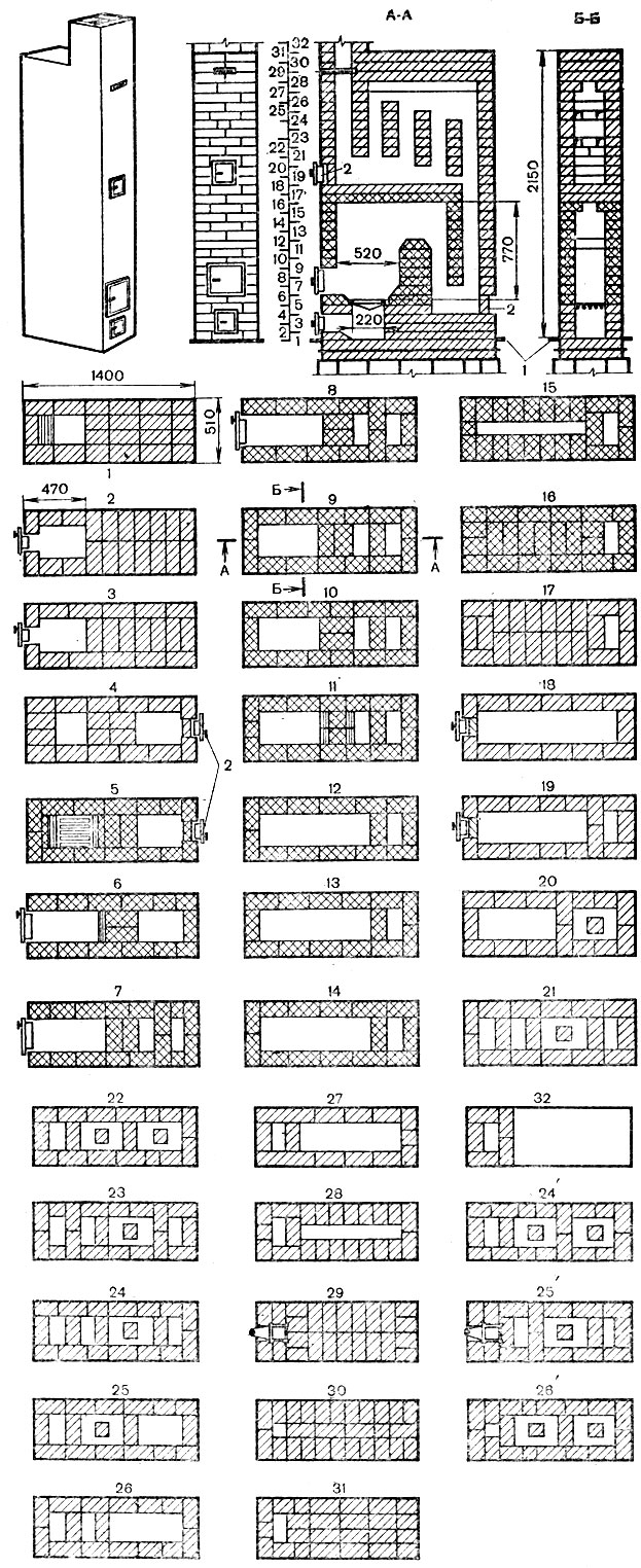
Materials: ordinary brick - 380 pieces; refractory brick - 190 pieces; ordinary clay - eleven buckets; refractory clay - 57 kg; sand - ten buckets; grate 250×252 mm; combustion door - 250×205 mm; blower door 130×140 mm; two cleaning doors - 130×140 mm; two smoke valves - 130×130 mm; pre-furnace sheet - 500×700 mm; waterproofing (roofing felt) - 1450×550 mm (2 sq. m).
The laying is carried out according to the procedures, with careful bandaging of the seams. Refractory brick can be replaced with good ordinary brick. If shading is shown inside the channels, this indicates hewn brick. You should carefully examine the sections of the stove.
From the twentieth to twenty-fifth rows inside the channels large sizes half the brick is laid, which is necessary for installing partitions in the upper part of the furnace. From the thirty-second row, the laying of a pipe of five bricks begins, the channel size is 130 × 260 mm.
For rooms with a height of 2.7 m, 24" 25" and 26" rows must be inserted between the twenty-third and twenty-fourth rows.
Plastered stove with heat output 3020 kcal/h
The heating stove (Fig. 77) has dimensions: width - 770 mm, length - 1020, height - 2150 mm. The front and back walls account for 610 kcal/hour, and the right and left walls account for 900 kcal/hour.
Materials: ordinary brick - 400 pieces; refractory brick - 220 pieces; ordinary clay - thirteen buckets; refractory clay - 66 kg; sand - ten buckets; grate - 250×180 mm; combustion door - 200×205 mm; blower door - 130×140 mm; two cleaning doors - 130×140 mm; two valves - 240×130 mm; pre-furnace sheet - 500×700 mm; waterproofing (roofing felt) - 770×1020 mm (2 sq. m). The laying of the stove is carried out according to the procedures, with careful bandaging of the seams. Refractory brick can be replaced with ordinary selected brick. In the fifth and sixth rows, the brick is cut off, as evidenced by the shading in the picture inside the firebox and near the grate. To close the oven, two valves are installed (see rows 25 and 29). The pipe is placed in five bricks with a channel 130x260 mm.
For rooms with a height of 2.7 m, between the twenty-sixth and twenty-seventh rows, it is necessary to insert 27", 28" and 29" rows.
Plastered stove with heat output 3850 kcal/h
The heating stove (Fig. 78) has dimensions: width - 1020 mm, length - 1020, height - 2150 mm. The front wall accounts for 1000 kcal/h, and the rest - 950 kcal/h.
Materials: ordinary brick - 552 pieces; refractory brick - 206 pieces; ordinary clay - fourteen buckets; refractory clay - 91 kg; sand - thirteen buckets; grate - 252×300 mm; combustion door - 250×205 mm; blower door - 250×140 mm; five cleaning doors - 130×140 mm; two smoke valves - 240×130 mm; pre-furnace sheet - 500×700 mm; waterproofing (roofing paper) (2 sq. m).
The laying of the stove is carried out according to the procedures, with careful bandaging of the seams. Refractory brick can be replaced with selected ordinary brick.
From section A-A it can be seen that the front and back walls are made of refractory brick 3/4 (19 cm) thick. One row of masonry is laid flat, the other - on the edge, with a thickened seam. If it is possible to line (cover) the firebox with refractory brick, then it is placed on the edge. The walls are made of ordinary bricks in exactly the same order. It should be remembered that the use of thickened masonry made of refractory brick is associated with high temperatures in the firebox, which quickly destroys ordinary bricks.
Almost half of the furnace is made of refractory brick. Valves are installed in the twenty-fifth and twenty-ninth rows. For rooms with a height of 2.7 m, between the twenty-sixth and twenty-seventh rows, two more rows of masonry of the twenty-fifth and one twenty-sixth row are inserted. The pipe is made of five bricks with a channel of 130×260 mm.
Oven in a metal case with a heat output of 3920 kcal/h
The heating stove (Fig. 79) has dimensions: width - 890 mm, length - 1140, height - 2150 mm. The heat transfer for each wall is not indicated.
Materials: ordinary brick - 400 pieces; refractory brick - 253 pieces; ordinary clay - thirteen buckets; refractory clay - 110 kg; sand - twelve buckets; combustion door - 250×205 mm; blower door - 250×140 mm; five cleaning half-doors - 130×160 mm; two smoke valves - 240×130 mm; grate - 300×252 mm; pre-furnace sheet - 500×700 mm, roofing steel for the case 10 sq. m, only 2 sq. m for waterproofing.
After making the case, it is coated with fire-resistant varnish on the inside and outside. The case consists of several links. The lower, or first, link is made no more than 700 mm high. At a higher height, it is very inconvenient to work in it when laying the first rows. The case must be carefully marked and equipped with places for the blower, doors, cleaning, and latches. On the inside of the case, 6-10 clamps made of strip steel are placed to secure the case to the furnace body. The front and rear walls are laid in half, and the side walls in a quarter of a brick.
The first row is laid first and a case is put on it, or the case is placed first, and then the laying is done. The brick should adhere to the case as tightly as possible and, best of all, on a layer of clay mortar, since the air gap between the case and the masonry greatly reduces heat transfer. The masonry is carried out according to the order, with bricks being cut in the required rows. As soon as the first link is filled with masonry, the second is put on it and placed further, etc. The pipe is placed in a five-piece with a channel of 260x130 mm. For rooms with a height of 2.7 m, 27", 28" and 29" rows must be inserted between the twenty-sixth and twenty-seventh rows.
Tiled stove with heat output 4150 kcal/h
The heating stove (Fig. 80) has dimensions: width - 1020 mm, length - 1020, height - 2150 mm. The heat transfer for each wall is not indicated.
![]()
Materials: ordinary brick - 425 pieces; refractory brick - 155 pieces; ordinary clay - fourteen buckets; refractory clay with fireclay - 75 kg; sand - thirteen buckets; combustion door - 250×205 mm; blower door - 250×140 mm; six cleaning doors - 130×140 mm; two smoke valves - 240×130 mm; grate - 300×252 mm; pre-furnace sheet - 500×700 mm; terracotta corner tiles - 52 pieces, straight tiles - 162 pieces, roofing felt for waterproofing - 2 sq. m.
Before laying the stove, the tiles are sorted by color and size, individual inaccuracies are sharpened, and the bricks are sorted. First of all, each row is laid without mortar, corrected, disassembled and then sequentially laid on mortar.
The tiles are fixed in the masonry as described earlier. The masonry is carried out strictly according to the order, with careful bandaging of the seams. The pipe is placed in five bricks with a channel 260x130 mm.
For rooms with a height of 2.7 m, 27", 28" and 29" rows are inserted between the twenty-sixth and twenty-seventh rows.
After laying, the front surfaces are cleaned of dust and dirt, the seams between the tiles, depending on the color, are filled with white or tinted gypsum mortar.
*** To view drawings, click on the picture
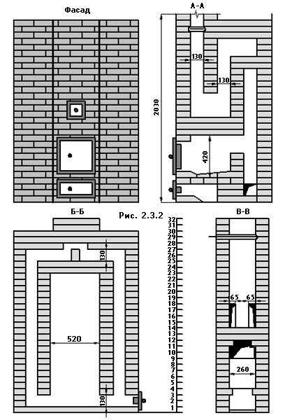
Rectangular heating stove with increased heat output. For heating large rooms, it is recommended to install rectangular stoves with increased heat output. The oven, like the one described above, is simple in design. An idea of her design features gives rice 2.3.2, which shows the facade and vertical section of the furnace.
The firebox design is the same as that of the 0-2 Giproaviaprom stove. It can burn any solid fuel. The flue gases from the firebox rise through the vertical channel, but do not reach the furnace roof, but, having been reflected from the intermediate ceiling, fall to the bottom of the furnace, where through the underpass they enter the rear lifting channel, along which they rise to the furnace roof. After then passing through a series of successive revolutions, the gases escape into the chimney. The oven has bottom heating. Due to the large area of the heated outer walls, the heat transfer of the furnace with two fireboxes per day is 6400 W.
Smoke valves are installed on the 32nd and 36th rows. The second valve is not shown in the drawing. The cross-section of the chimney channel is above the horizontal groove (13x13 cm).
For laying the furnace it is required:
- Ordinary brick - 578 pcs.
- Blower door 14x25 cm - 1 pc.
- Fire door 26x27 cm - 1 pc.
- Cleaning doors 13x14 cm - 3 pcs.
- Viewing valves 25x13 cm - 2 pcs.
- Ordinary clay - 0.45 m 3
- Sand - 0.45 m 3
- Roofing felt for waterproofing - 3 m
For laying the furnace it is required:
- Red brick - 490 pcs.
- Grate 25x25 cm - 1 pc.
- Fire door 28x27 cm - .1 pc.
- Blower door 14x13 cm - 1 pc.
- Cleaning door 14x13 cm - 1 pc.
- Viewing valve 25x13 cm - 1 pc.
- Furnace wire Ø2 mm. - 3 m
- Ordinary clay - 0.4 m 3
- Sand - 0.4 m3
- Pre-furnace sheet 70x50 cm - 1 pc.
- Roofing felt for waterproofing - 3 m 2
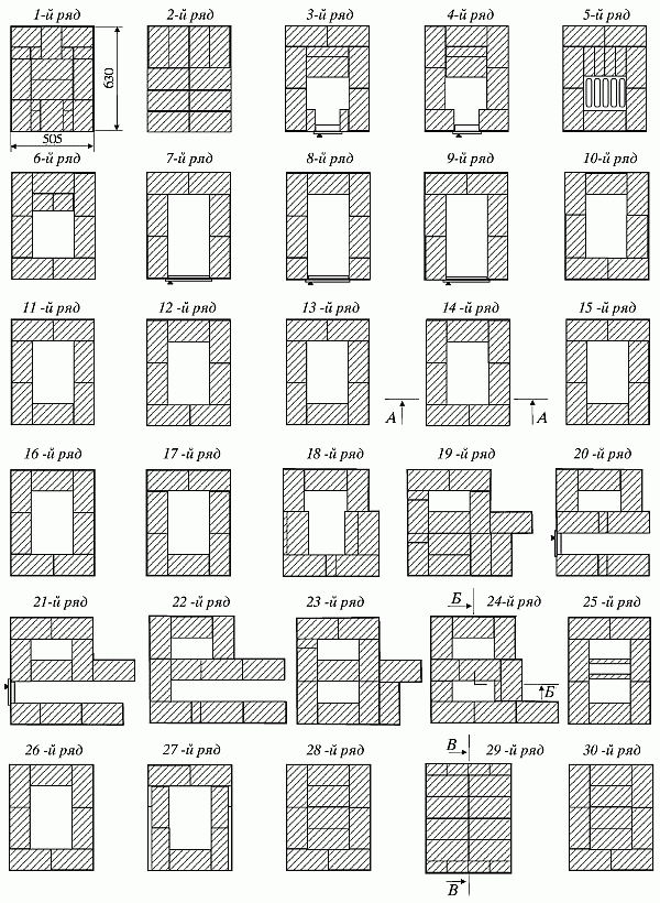
The furnace is laid in the following order (see Fig. 2.3.4 - 2.3.6).
1st row. The bottom of the ash pan is formed in the front part. The brick lying in the blower door is beveled.
2nd row. They install a blower door. A channel is formed in the rear part, which is closed on one side with a blank wall and on the other with a cleaning door.
3rd row. The bricks in the front protruding part are laid out in such a way that when laying the next row, the vertical seams are tied.
4th row. The walls of the ash chamber in this row are 18 cm thick. Increasing the thickness of the walls is necessary so that after laying the grate there are no gaps between its edges and the walls of the firebox. In the rear part, cuts begin that separate the lifting vertical channels.
5th row. Lay the grate.
6. 7, 8 and 9th rows. In the front part, a firebox with a plan size of 26x51 cm is laid out. On the 8th and 9th rows, the firebox is connected to the fire chamber.
10th row. Cover above the fire door.
11,12 and 13th rows. Firebox shut-off device at outlets. In the rear part there is a continuation of the laying of the fire chamber and lifting channels.
14th row. A cleaning door is installed on the façade side. An upper chamber is formed in the front part. Support post size. 1/2x1/2 brick divides it into the chamber itself, connecting channels and the base of the chimney.
15, 16, 17th rows. The masonry of these rows differs from the previous one only in the arrangement of bricks for bandaging the vertical seams.
18,19,20, 21st rows. The base of the cut is applied through the support column between the upper chamber and the chimney. Otherwise the masonry is the same as the previous rows.
22nd and 23rd rows. Cover the lower heating chamber.
24th and 25th rows. Vertical lifting channels are connected to the upper chamber through a channel. Install a cleaning door to clean the horizontal channel.
26, 27, 28 and 29th rows. Overlap device. On the 28th row a view gate is installed. Starting from the 30th row, lay a chimney with an internal channel of 25x13 cm.
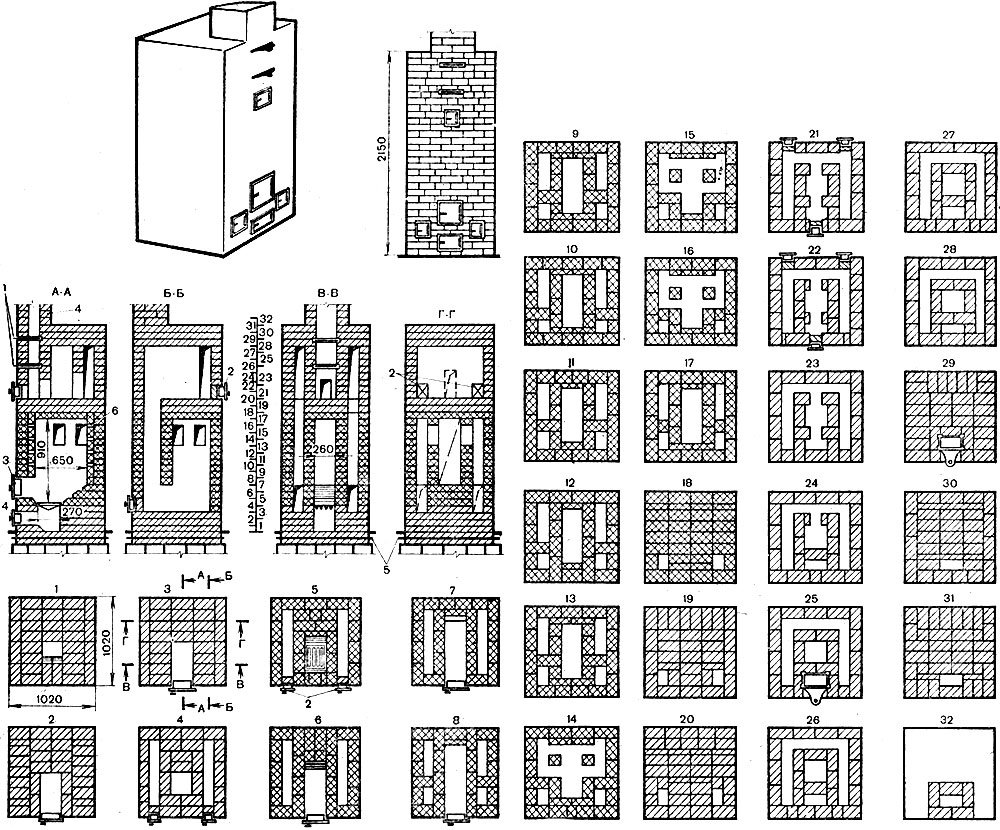
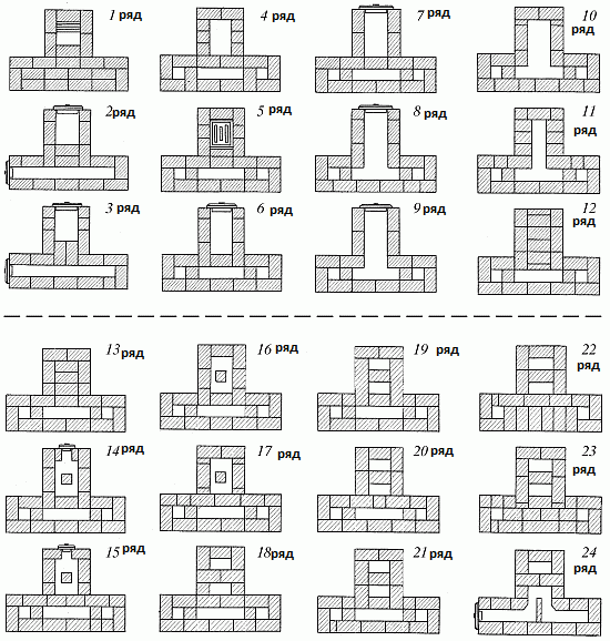
Design. The dimensions of the stove in plan are 51x89 cm, height 238 cm. Any fuel can be burned in it. The firebox is located in the lower part of the stove; its walls are also the walls of the stove itself, which provides bottom heating. Flue gases enter the vertical channel, reflected from the ceiling.
Material. To lay the furnace you need: brick - 355 pieces, including fireproof 110 pieces.
Laying the stove in rows. 1st row - in the front part, the bricks are laid out with butts, the corner bricks are chopped off to 3/4 of the brick, and the upper edges of the 2 middle ones are cut off, forming a slope inside the masonry to the bottom of the ash pit. The slope is shown in the section along A-A. In the rear part of the row, the space between the outer wall of the furnace and the rear wall of the ash pit is filled with dry sand. Backfilling is carried out up to the 3rd row inclusive.
Rice. 1. Heating rectangular stove 1 – ash pan; 2 – blower door; 3 – combustion door; 4 – cleaning; 5 – ceiling; 6 – chimneys; 7 – heat channel; 8-fuel tank; 9 – grate; 10 – under
2nd row - a blower door is placed in the center of the front wall. Corner bricks to the right and left of it are up to 3/4 bricks, the rest of the masonry is made of full-size bricks.
3rd row - after laying the bricks of this row, a steel strip 35 cm long and 4 cm wide is placed above the front of the ash pan, which serves as a support for the bricks that cover part of the ash pan on the next row.
Rice. 1. Laying a rectangular heating stove
4th row - cover the front part of the ash pan.
In the back part of the row, the sand backfill is laid with bricks.
Rice. 2. Laying a rectangular heating stove
5th row - a grate is placed on the hole above the ash pan. Bricks hewn at the back and front form slopes for rolling coals onto the grate.
6th row - a fire door is placed in the center of the front wall. The bricks of the rear wall are hewn with a slope inward and form one inclined plane with the bricks of the previous row. 7th - 12th row - laying the firebox. 13th row - laying outlets to cover the firebox. The front part of the side walls is laid out from 3/4 bricks.
14th - 15th row - overlap above the firebox. A hole is left in the rear part connecting the firebox with the vertical channel - hailo. 16th row - they install a cleaning door, block it from behind with a “half” laid on the edge. The shelf behind the door is covered with a layer of clay-cement mortar to completely isolate the firebox from the smoke channels located above. 17th - 20th row - laying vertical smoke channels.
21st - 22nd row - connect the lifting smoke channel coming from the firebox with the lowering channel. Here, gases from the firebox pass through the cut separating the channels into the middle lower channel, along which they reach the 18th row, and through the undercut they enter the front lift channel. 23rd - 24th row - overlap the middle and rear channels.
25th - 26th row - place a cleaning door at the base of the chimney, as a result, a tuck is formed from the middle channel of the second tier to the chimney. 27th - 30th row - laying the smoke channels of the second tier, of which the rear one is the beginning of the chimney.
On the 28th row the first view gate is installed. On the 30th row, the second cycle of revolutions is completed. Here, the flue gases from the front lifting channel pass into the middle lowering channel and, having descended along it to the underside, on the 26th row they enter the chimney.
31st row - install outlets to cover the furnace. Rows 32 - 34 - furnace roof. The bricks are laid so that all vertical seams of the first row of the roof are covered.
On the 32nd row a 2nd view gate is installed. Installation of 2 view valves reduces heat loss from the furnace. If there are no valves, a round view is installed on the 32nd row. Row 35 and subsequent ones - laying the chimney.
Heating rectangular stove
- ordinary clay - 0.2 cubic meters;
- sand - 0.2 cubic meters;
- fireclay clay - 11 kg;
- brick - 355 pcs. (including - 110 pcs.);
- pre-furnace steel sheet (50 x 70 cm) - 1 pc.
- fire door (25 x 20.5 cm) - 1 pc.;
- roofing felt or roofing felt for waterproofing - 1 sheet.
- 1st row - we lay out the front wall with pokes, fold the corner bricks to 3/4. Two middle bricks must be cut along the upper edges to create a slope inside the masonry to the bottom of the ash pit. The space between the rear wall of the ash pan and outer wall fill the ovens up to the 3rd row inclusive with dry sand;
- 2nd row - we install the blower door in the center, and on the sides of it we lay “three-four” bricks, all other bricks are full-size;
- 3rd row - masonry is being built up. After all the bricks are laid, we place a 4 x 35 cm steel strip over the front of the ash pan (in the 4th, the ash chamber overlap is placed there);
- 4th row - we cover the ash pan. We lay the sand backfill in the back with bricks;
- 5th row - we place a grate over the ash pit, while hewn bricks are laid behind and in front to create a slope along which the coals will roll onto the grate;
- 6th row - install the combustion door in the center of the front wall of the stove. It is necessary to ensure that the bricks of the rear wall are hewn in the same inclined plane with the slopes of the previous ones;
- 7-12 rows - we lay half a brick with bandaging of the seams, lay out the firebox;
- 13th row - to cover the firebox we make outlets, for this we place part of the side and front wall in “three-four” formations;
- Rows 14-15 - create an overlap over the firebox. To connect the firebox and the vertical channel, we leave a hole (hilo) in the rear part;
- 16th row - place half a brick on the edge and prop the door on the right side with it. After this, we cover the shelf behind it with clay-cement mortar; this is necessary to isolate the firebox from the smoke channels located above;
- 17-29 rows - lay out vertical smoke channels;
- Rows 21-22 - connection of the lower and lift channels. It should be noted that it is in this place that the cut should end, which separates the middle lower channel and the rear lift channel coming from the firebox;
- 25-26 rows - we make a twist from the middle channel of the second tier to the chimney and install a cleaning door;
- 27-30 rows - lay out the smoke channels of the second tier (the view valve should be installed on the 28th row);
- 31st row - we create outlets for covering the furnace;
- 32-34 rows - the furnace roof is finally installed with dressing of the seams (the second view valve should be installed on the 32nd);
- 35 and to the end - (pipe cross-section 13x13 cm).
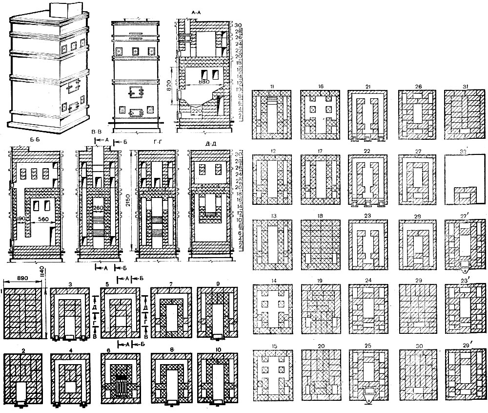
This stove is convenient for heating large rooms. From the firebox, smoke enters the hailo, from where it enters the rear chamber. Part of the heat remains on the walls of the furnace, then the smoke from the ceiling falls down, moves through the lifting channels into the upper chamber and, having given off heat, falls down, where it enters the channels to the chimney.
Heat output - 5.3 kW.
- ordinary clay - 0.4 cubic meters;
- sand - 0.4 cubic meters;
- brick - 490 pieces (red);
- grate (25×25 cm) - 1 pc.;
- blower door (14×13 cm) - 1 pc.;
- pre-furnace sheet (70 x 50 cm) - 1 pc.;
- fire door (28 x 27 cm) - 1 pc.;
- view latch (25 x 13 cm) - 1 pc.;
- cleaning doors (14 x 13 cm) - 3 pcs.;
- roofing felt for waterproofing - 3 sq.m;
- oven wire (diameter 2-3 mm).
Laying is done as follows:
- 1st row - lay out the bottom of the ash pan. Please note that the brick that is placed behind the blower door must be hewn towards the back;
- 2nd row - install a blower door and make a channel in the rear with a cleaning door on one side;
- 3rd row - do the same as the previous one, with ligation of the seams;
- 4th row - we put cuts for lifting vertical channels in the back and increase the thickness of the walls to 18 cm;
- 5th row - laying the grate;
- Rows 6-9 - place a firebox (26 x 51 cm) in the front of the stove;
- 8-9 rows - we make a connection between the firebox and the fire chamber;
- 10th row - close the combustion door;
- 11-13 rows - we continue to lay the fire chamber, not forgetting to make outlets to cover the firebox;
- 14th row - install a cleaning door in the front wall. To divide the front space into a chamber, the base of the chimney and connecting channels, we make a column half the size of a brick;
- 15-17 rows - do the same as the 14th, with ligation of the seams;
- Rows 18-21 - lay out the base of the cut of the upper chamber and the chimney, it should rest on the column;
- 22-23 rows - we overlap the lower heat chamber;
- 24-25 rows - we connect the upper chamber and the vertical lifting channel using a horizontal channel (the cleaning door of the horizontal channel is placed on the 24th);
- Rows 26-29 - finally installing the furnace roof (the view valve is installed on the 28th);
- 30 and to the end - lay out the chimney (pipe cross-section 13 x 25 cm).
Round stove in a metal case
This type of stove begins to give off heat soon after lighting and heats up evenly.
Dimensions - diameter 65 cm, height 229 cm. Heat output - 1.75 kW.
Materials for laying a stove with your own hands:
- ordinary clay - 0.05 cubic meters;
- sand - 0.03 cubic meters;
- brick - 260 pieces (including refractory brick - 65 pieces);
- grate (18×25 cm) - 1 pc.;
- blower door (13×14 cm) - 1 pc.;
- pre-furnace sheet (50 x 70 cm) - 1 pc.;
- fire door (21 x 25 cm) - 1 pc.;
- view latches (13 x 13 cm) - 2 pcs.;
- cleaning doors (13 x 14 cm) - 2 pcs.;
- roofing felt or roofing felt for waterproofing (diameter 85 cm) - 2 sheets;
- fireproof clay - 11 kg;
- roofing steel for the case - 6.5 sq.m.
If you set out to create a stove of this type with your own hands, then before starting to lay the stove itself, you should mark and cut holes in the steel sheets for the blower, combustion and cleaning doors, as well as for the view valves. The construction of the stove begins with the installation of the first casing drawer on a previously prepared base. Next, you need to check the verticality of the installation and fill the seams between the drawer and the base with clay mortar. Then inside the drawer it is performed brickwork, according to the plan presented in the figures. One of the most important advantages of stoves in metal cases is the complete gas-tightness of the walls and quite simple internal structure. The case most often consists of only three drawers, successively mounted on each other.
List of required tools
- furnace hammer;
- pick;
- trowel;
- washbrush;
- rule;
- level;
- spirit level;
- square;
- wooden oar;
- wooden shovel;
- steel shovel;
- strukaltse.
Tools such as a sledgehammer, a whetstone, a scarpel and a rasp are used as needed. For laying unlined simple stoves, it is enough to have a stove hammer, usually a weight, a trowel, a level, a square, etc.