Ventilation is important for any home, which will prevent mustiness, unpleasant odors and dampness from entering it. One way to get rid of this is to provide ventilation ducts in brick walls. With a hidden “hood” there will be a good microclimate in the house.
Indispensable rules of the device
 Exhaust ventilation channels are installed when laying the walls of the house, inside them. If the wall is 38 cm thick - in 1 row, if 64 cm - in 2 rows. Traditional section - 140x140 mm. The same solution is used as for masonry at home. It is allowed to use a solution of clay and sand.
Before you make a ventilation duct in a brick wall, you need to have solid ceramic bricks at your disposal. You will need a template that you can make yourself. This is a board (length, width, thickness - 2.5 m x 140 mm x 25 mm), in which cutouts are made corresponding to the size of the ventilation ducts and their location on the wall. We need inventory buoys - hollow boxes made of boards. Their cross section is like that of a channel, the height should be 8-10 bricks. Cleaning of the masonry will be done by mopping, checking for “cleanliness” - with a test ball on a cord with a diameter of 100 mm.
The masonry is done vertically. It must be moved away from the door opening as well as from the wall joints by no less than 380 mm. The adjacent channel and chimney are insulated with each other using heat-resistant materials and the walls of the channel are enlarged.
Practical experience
The installation of a ventilation duct is made taking into account the following important points:
And if without masonry
A homemade ventilation duct in brick walls is made using pipes. But even in this case, it is necessary that each room has its own air duct. One of the exits should be at a height of two meters above the foundation (higher is possible) inside outer wall(sucks in air from the street). The second is on the roof (removes air from the house). All channels are connected to it. The pipe should rise one meter above the roof. The inlets for the grilles are located under the ceiling, no lower than 10 cm. They are closed with dampers that regulate the air flow.
You can combine hoods from the sauna-kitchen, bathroom-toilet. All four can be combined in the attic. It is important that there are reliable seals at the joints. Information “in a bouquet” can only be done if the services are located on one side of the house. IN one-story house they can be mounted in the ceiling (they go out to the roof through the attic). Pipes in the attic should be insulated.
For natural ventilation risers, the diameter of the pipes is 125 x 150 mm, for forced ventilation - 100 x 125 mm. The choice of materials depends on what the owner likes and the price. They can be made of polymers, galvanized, asbestos cement, concrete. When installing, pipes are lowered into the space between the walls and cemented. The tightness at the point where the ventilation pipe exits onto the roof is important. To do this, use a passage element made of rubber or silicone. The air duct and the exhaust outlet are connected by a corrugated pipe.
How to make pipes yourself
You can make a ventilation duct in a brick wall yourself, even if it is thin. With a partition half a brick thick, an asbestos-cement pipe with a diameter of 120 mm (internal - 100) will “fit in”. The opening in this case should be 130 mm wide. By lowering the pipe into it, it is strengthened cement mortar.
In the absence of a pipe, it is made like this: two large half-waves of slate of the required size are fastened with wire. It is attached to a brick cabinet, which is laid out flush with the partition. But there is another way: on the sides of the partition in its upper part, lay a couple of bricks on the edge and install the structure. A hole is cut out in the lower part for the ventilation grille, where it is attached. At the end - plastering. The part that ends up in the attic should be insulated with asbestos (foil will also do). On the roof it should be no closer than a meter from its highest point.
There are even thinner openings - a quarter of a brick. In this case, the cabinet will be replaced with a structure that can be made from strips of flat slate (20 cm wide). They are inserted into the canal, spread out and tied with wire, and plastered.
Hood connection
In the kitchen, only the ventilation installed in the wall may be “missing”, especially if you cook often and the kitchen is small. A hood helps out by removing unpleasant air from the kitchen. It is important to connect it correctly to the ventilation duct. It is desirable that the distance to the ventilation shaft be minimal. Otherwise, the effect of the hood will be reduced. And long air ducts look ugly.
For connection, special air ducts and adapters are required. The elements are connected hermetically. A number of rules are important for safety and efficient operation. When connecting an exhaust pipe, it should not block the entire ventilation duct: when it is not working, the main ventilation operates from air draft. To do this, you need to remember to place a grill over the entrance of the exhaust pipe.
To ensure that the hood does not fail, the air must not be obstructed. This is why it is important to keep the duct length shorter. And it’s better to forget about turns altogether. The smoothness of the pipe will also contribute to high-quality traction. Therefore, corrugated pipelines, which are preferred due to their flexibility, still hinder the air flow. If you can’t do it, you need to smooth out the turns. Danger: if a gas heater is used in the kitchen, the hood must not be vented into its smoke duct
The most common mistakes
- The ventilation duct is not installed in the kitchen, bathroom, bathrooms, and closets without windows.
- Instead of a channel, there is a hole in the wall, closed by a grille. This does not provide traction, and therefore is not effective.
- The windows and doors are hermetically sealed and there are no ventilators. In such conditions, ventilation does not work, which will be indicated by unpleasant odors, condensation, and mold.
- “Overkill” with ventilation. Forced ventilation, if there is a special hood, for example, a fireplace, is not allowed.
- There is no hood at all in the room with the fireplace. A properly functioning fireplace chimney is safe. But when the fireplace is lit, smoke can enter the room; it is better to have a separate ventilation duct in it.
- There is no hood in the room, which is separated from the rest by two doors. “Overcoming” them with air flow is sometimes completely impossible, as is effective ventilation.
- Uninsulated channel. If the channels are in external walls, they must be insulated, otherwise the traction force is lost.
- Gas pipes must not be installed in the wall. Do this only in fines with screens that have holes for ventilation.
- Deviation of the vertical channel may interfere with ventilation. Maximum 30°. If the job is done, there is only one way out - install an additional fan. Just not in a room where there is a fireplace!
Maintaining the required microclimate parameters in a room is impossible without proper organization of air exchange. Ventilation ducts are designed to provide the required air replacement rate in the room, so their arrangement is planned at the building design stage. The most common and reliable material used for these purposes is brick.
Ventilation ducts: the need for arrangement
Building structures are usually located in walls (inside). In this case, the brick is laid in one row if the wall thickness does not exceed 38 cm, and in 2 rows - with a wall surface 64 cm thick. One of the ventilation elements - the exhaust pipe - should be formed with walls of 2.5 bricks. It is this size that allows you to maintain a constant temperature regime inside the shaft and protect the passing air from cooling.
Multi-storey buildings are characterized by inclined rather than orthogonal ventilation systems. At the same time, the level of their outlets reaches 1 m. The maximum deviation of a vertical shaft without deteriorating ventilation performance is no more than 30 degrees.
Laying channels: technical features
Laying brick ventilation ducts begins with design work. For a private house, at the initial stage of drawing up a project, one cannot deviate from the requirements set out in SNiP 2.04.05-86.
- The construction of air ducts without an approved design is prohibited.
- Smoke and ventilation outlets must not be combined.
- For wall thicknesses up to 380 mm, the masonry is single-row.
- If the thickness of the wall partition is 640 mm, the masonry is done in 2 rows.
- Before construction begins, the outline of the channel is drawn using a template, etc.
The dimensions of ventilation shafts are calculated in such a way as to ensure the required air exchange rate in the room. Power is taken as the initial data heating system heating the premises:
- Channel size (cm): 14x14 – with a power of no more than 3.5 kW;
- 14x20 (cm) – 3.5 – 5.2 kW, respectively.
The type and parameters of ventilation passages in the brickwork depend on the purpose of the building, but basically it is a square cross-section vertical shaft (140x140mm), laid out in 2 bricks in interior walls Oh. You need to focus on the following parameters of a single brick: its length is 250 mm, width 120 mm, height 65 mm.
Attention! The exhaust duct, along with the removed air, carries heat outside. A small structural detail inside it - a bend in the form of a brick staircase - will become an obstacle to the outflow of warm air masses.
In houses with stove heating Channels for air exchange are best placed parallel to the stove chimney, close to it. Air heated from exhaust gases improves draft and efficiency of their operation. If it is difficult to do this structurally, then the outlet installed in the outer wall is insulated. This ensures good traction. For a constantly operated fireplace, an independent ventilation duct must be provided in the house. Through it, smoke entering the room from fuel combustion is removed to the street.
Brick for masonry and notes on working with it
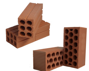
For brick walls, solid stone is usually used. It is possible to use hollow facing bricks, but with voids filled with clay or mortar.
Attention! Sand-lime brick is not used to form ventilation ducts, because... sudden temperature changes provoke its destruction.
The brick is fixed in the channels with the same mortar that was used for the construction of the internal walls. In order for the batch to be of sufficient strength, the following proportions must be observed when preparing the solution:
- purified construction sand – 3 parts;
- cement M500 – 1 part.
Water is added in measured portions to the dry, pre-prepared mixture with constant stirring. The consistency of the mixture should be such that when the container is tilted at 45 degrees, it does not spill out.
The formation of a ventilation duct often requires the use of non-standard size bricks in cases of bandaging seams, at the junction of walls, etc. For their mechanical processing, the following is used:
- chopping with a trowel or pick-hammer;
- Bulgarian;
- mechanism for cutting bricks.
In order to save money, scraps, material with broken corners, chips, etc. are processed.
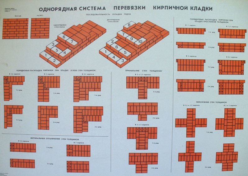
Algorithm for laying a ventilation duct
- Careful study of the drawing.
- Applying markings using an inventory folding template. If it is not there, openings are made in a board with dimensions (mm): 140x2500x25, identical to those marked on the wall plan.
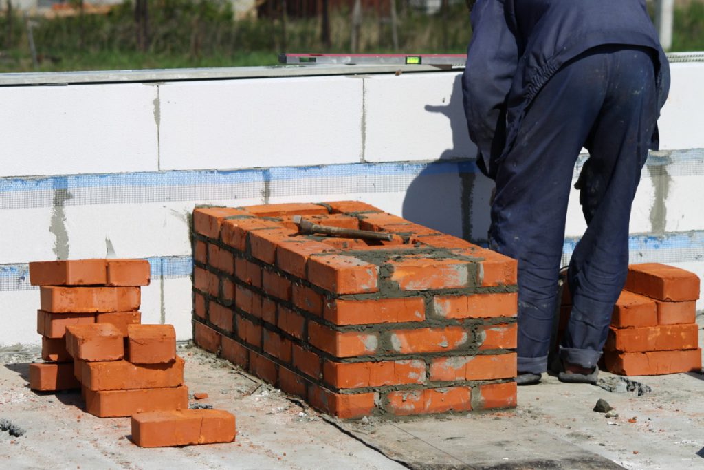
- The brick is laid strictly according to the level, for which buoys or a box made of boards with the dimensions of the channel are used. The straightness of surfaces and corners must be maintained.
- If the air temperature is high and the brick is dry, it is necessary to moisten it with water to improve adhesion between the material and the mortar.
- 3 or 4 rows of masonry are formed.
- Buoys are installed - bricks laid level in the cross section of the channel. They protect it from debris during work and maintain the desired shape of the hole.
- The buoy moves every 7 or 8 brickworks with a single-row or multi-row ligation system.
- If there is a possibility of fuel combustion products entering the premises, as well as nearby ventilation systems along with the supplied air, then it is better to do the masonry using the “end-to-end” method.
- Ensure that the thickness of the seams is maintained.
- Seal them all thoroughly.
How much does it cost to build a masonry
Despite the popularity of monolithic and frame housing construction, masonry from piece materials is still in demand in construction. Experienced craftsmen with certain skills and knowledge can do the job well. If it is planned to invite specialists to perform this type of work, then an estimate must be drawn up. It is affected by:
- number of storeys of the building;
- area of premises;
- geometric complexity of channels;
- performing dressings with existing masonry;
- the need to finish sedimentary seams;
- type of material and its price, etc.
At the same time, the speed of work does not depend on such characteristics of the brick as strength grade, resistance to freezing, and color preferences. Therefore, these parameters do not affect prices.
Refined calculations take into account the real costs of working time for each type of work performed (man-hours). After timing the execution of each construction operation, its exact duration is determined. Having this data, as well as the average salary for a specific region, you can calculate the hourly rate using the formula:
R – tariff (rubles);
C – salary size (average) (rubles/day);
V – duration of work per day (hour).
Example
The crew carries out the laying, working 12 hours a day. With indicator C = 900 rubles/day, the cost of work for 1 hour will be: 900/12 = 75 rubles per hour.
It is also taken into account that the tariff for laying, for example, hollow one-and-a-half bricks will be significantly lower. This is justified by the higher speed of work completion. The number of piece units per unit of masonry volume in this case will also be less. All this explains why prices for this type of service differ in different regions and at different facilities.
A properly executed ventilation system in the house will help maintain optimal microclimate parameters, promote cleanliness of the air in it, and prevent the formation of dirt in the ducts and heat loss.
Chimneys are divided according to their design and location:
- on wall chimneys - installed inside solid brick walls
- main chimneys - laid out in the form of a free-standing brick riser
- mounted chimneys - installed directly on stoves
If the room has solid stone walls, then the installation of internal wall chimneys is most convenient and economical, since they do not require additional building materials and are laid out simultaneously with the walls.
Basic Requirements
For each furnace, as a rule, a separate chimney or duct (hereinafter referred to as the pipe) should be provided. Since when two stoves are fired simultaneously, the stove on the lower floor, with a stronger draft, will interrupt the top one, preventing the free exit of smoke from it.
It is allowed to use a common chimney for two stoves installed on the same floor, provided that a cut-out is installed in the form of a transverse wall between the chimneys at a height of at least 75 cm. In this case minimum size The cross-section of the common chimney channel must be at least 1x0.5 bricks.
In houses with stove heating the following are not allowed:
a) a device for exhaust ventilation with artificial impulse, not compensated by inflow with artificial impulse
b) smoke removal into ventilation ducts and installation ventilation grilles on smoke ducts
Chimneys should be located in the internal walls of the building. Laying them in external walls is less economical and creates difficulties during operation. Passing through chimneys in the outer wall, the gases give off some of the heat to the unheated room, and in the atmosphere due to the low temperature atmospheric air the gases are cooled excessively, which impairs draft. At the same time, tarry substances are released from the gases, which penetrate through the masonry and are deposited on the external structure of the house.
If the chimney riser is forced to be located in an external wall, the chimney wall must be thickened. The thickening of the wall is done in the form of pilasters (square or rectangular projections on the wall).
The minimum thickness of the masonry between the chimney and the outer surface of the wall is taken depending on the design temperature of the outside air:
- at t=-20°C and above - 38 cm (1.5 bricks)
- from t=-20°С to t=-30°С – 51 cm (2 bricks)
- from t=-30°С and below - 65 cm (2.5 bricks)
For laying the foundations of stoves, hearths and chimneys, the same materials are used as for the foundations of a house; for the main masonry of stoves, hearths, chimneys and channels in the walls - ordinary clay brick (solid).
If the walls are made of sand-lime brick, cinder blocks, etc., areas with smoke channels should be laid out of ordinary (solid) clay red brick.
Smoke pipes (ducts) or chimneys for stoves
The height of chimneys placed at a distance equal to or greater than the height of a solid structure protruding above the roof should be taken:
- not less than 500 mm - above a flat roof
- not less than 500 mm - above the roof ridge or parapet when the pipe is located at a distance of up to 1.5 m from the ridge or parapet
- not lower than the ridge of the roof or parapet - when the chimney is located at a distance of 1.5 to 3 m from the ridge or parapet
- not lower than a line drawn from the ridge downwards at an angle of 10 to the horizontal - when the chimney is located from the ridge at a distance of more than 3 m
It is allowed to connect two stoves to one pipe, located in the same apartment on the same floor. Such placement may be allowed in exceptional cases, provided that the wall is insulated from the outside by thickening the masonry or protecting it with heat-insulating, fireproof materials (the insulation method must be provided for by the design).
Then the distance between the outer surface of the walls and the nearest inner surface of the channel is taken to be at least 640 mm (2.5 bricks). When connecting pipes, cuts should be made with a thickness of 0.12 m and a height of at least 1 m from the bottom of the pipe connection.
When the chimney is located in the middle of the room, the walls are laid out 1/2 brick thick, and when located near the cold outer wall of the building - a whole brick. The thickness of the walls of chimneys or smoke ducts at the point where they adjoin metal or reinforced concrete beams should be 130 mm.
The thickness of the walls of the channels in internal stone walls, as well as the thickness of the partitions (cuts) between the smoke and ventilation ducts must be at least 120 mm. Stoves, as a rule, should be placed near internal walls and partitions made of non-combustible materials, providing for their use to accommodate smoke ducts.
Smoke ducts may be placed in external walls made of non-combustible materials, insulated, if necessary, on the outside to prevent moisture condensation from the exhaust gases.
In the absence of walls in which smoke ducts can be placed, mounted or root chimneys should be used to remove smoke. Chimneys should be made vertical without ledges from clay bricks with walls at least 120 mm thick or from heat-resistant concrete with a thickness of at least 60 mm, with pockets 250 mm deep at their bases with cleaning holes closed by doors.
Internal surfaces chimneys should be smoother without mortar leaks in the seams and carelessly laid bricks. The chimney must be free of slopes and turns.
It is allowed to accept deviations of round chimneys at an angle of up to 30° to the vertical, with a deviation of no more than 1 m. Inclined sections must be smooth, of constant cross-section, with an area not less than the cross-sectional area vertical sections.
Experience shows that the cross-section of the chimney is from 1/10 to 1/12, and in more favorable cases up to 1/15 of the clear size of the combustion opening. In all cases, the cross-section of the chimney (if two stoves are connected to one pipe) must be at least 14x27 cm.
Brick chimneys
The cross-sectional area of rectangular chimneys (smoke ducts) depending on the thermal power of the furnace according to SNiP 2.01.01-82 should be taken as no less than:
- 140x140 mm - with a furnace thermal power of up to 3.5 kW
- 140x200 mm - with a thermal power of the furnace from 3.5 kW to 5.2 kW
- 140x270 mm - with a furnace thermal power from 5.2 kW to 7 kW
The cross-sectional areas of channels in brick chimneys must be multiples of the width of the brick. The mouths of brick chimneys to a height of 0.2 m should be protected from precipitation. The installation of umbrellas, deflectors and other attachments on brick chimneys is not allowed.
Round asbestos-cement, ceramic or metal chimneys
The cross-sectional area of round smoke ducts must be no less than the area of the indicated rectangular ducts. Metal chimneys must be removed from combustible roof structures by 700 mm. At the same time, within the attic, the pipes are insulated with a layer of asbestos at least 3 mm thick and plastered over a mesh with cement mortar, and in places where they pass through a combustible roof they are additionally equipped with special devices in the form of sandboxes.
The outlets of round chimneys and ventilation ducts located next to them in the walls are made with a slope of at least 60° to the horizon and a laying (attitude) of no more than 1 m. To connect stoves to chimneys, it is allowed to provide branch pipes with a length of no more than 0.4 m, provided :
a) the distance from the top of the pipe to the ceiling made of flammable materials must be at least 0.5 m if the ceiling is not protected from fire and at least 0.4 m if there is protection;
b) the distance from the bottom of the pipe to the floor made of flammable or slow-burning materials must be at least 0.14 m.
The pipes should be made of non-combustible materials, providing a fire resistance limit of 0.75 hours. and more. Smoke in the stove often occurs when the mouth of the pipe is blown out by a strong wind. To prevent this phenomenon, it is necessary to check the condition of the windproof device (deflector) above the head of the chimney, and if there is no device, install it.
For deflector options, see Fig.
Chimneys on buildings with roofs made of combustible materials should be equipped with spark arresters. For reasons fire safety A spark arrester is installed on the head in the form of a cap with a blank lid and wire mesh on the sides with a mesh size of no more than 3 mm.
You should know that weather vanes and deflectors can be installed on round pipes for solid fuel stoves. When burning gas, they CANNOT be installed, as water vapor condenses on them. This may cause ice dams to form.
For gasified furnaces, hoods of a simplified design are installed on the heads of round pipes. If the walls of the pipe are subsequently plastered or insulated with asbestos-cement slabs, then it is permissible to lay out the head 1/2 brick thick.
Smoke pipes (channels) for fireplaces
The main difference between a fireplace and a stove is the much larger cross-section for air access to the firebox, which is why large masses of air are sucked into the fireplace, which causes a decrease in the temperature in the flue (compared to stoves). Therefore, the traction force in a fireplace per 1 linear meter of flue height is less than in a stove.
To create normal draft, the height of the fireplace chimney must be correspondingly greater than that of the stove. To ensure sufficient draft during operation, it is IMPORTANT that the flue gases are cooled minimally as they move through the chimney.
The cornice formed in the narrow section of the chimney (the so-called smoke tooth) plays an important role and has a dual purpose. During the combustion process, it retains the cooled gases descending along the rear (colder) wall, preventing them from passing into the combustion space, because this may cause the rod to tip over.
Cold gases retained by the eaves are picked up by a stream of hotter gas flowing from the narrow section of the chimney that forms the front wall of the fireplace and the edge of the “tooth”, and are carried into the overlying chimney.
The second purpose of the cornice is to collect falling soot deposits. A cleaning door is installed in the immediate vicinity of the ledge on the inside, through which the chimney is periodically cleaned. A damper is installed in the neck at the level of the chimney cornice to regulate the draft and disconnect the fireplace from the chimney. To reduce heat loss, the walls of the fireplace chimney must be of sufficient thickness.
The most harmful effect on draft is caused by atmospheric air leaks into the chimney through leaks in the masonry, as well as non-working stoves connected to a common chimney, i.e. The chimney for the fireplace must be separate from all other ducts. All leaks must be identified and eliminated.
The next condition for maintaining normal draft (without describing the hydraulic properties of draft) is the construction of a chimney with a circular cross-section, then square and finally rectangular. This is explained by the fact that in right angles the movement of gases is difficult and, moreover, soot is often deposited in them.
Therefore, it is best to use asbestos-cement or ceramic pipes for installing chimneys. Due to the difficulty of fitting to the fireplace chimney, chimneys are most often laid out square.
Ventilation ducts
The thickness of the walls of the channels in the external walls of buildings is taken taking into account the design temperature of the outside air. The height of the exhaust ventilation ducts located next to chimneys, should be taken equal to the height of these pipes.
Dimensions of indentations (cuts) for stoves and smoke ducts.
A setback (cut) is the air space between the outer surface of a furnace, chimney or smoke duct, on the one hand, and a combustible wall, partition or other building structure, on the other hand. Leave an air gap (recess) along the entire height of the stove or chimney.
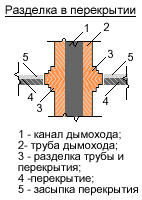 When installing grooves in floors, independent settlement of furnaces and pipes should be ensured. Supporting cuttings on structural elements of the floor is not allowed. The cutting height should be greater than the thickness of the ceiling by the amount of possible settlement of the building and 70 mm above the layer of combustible backfill.
Horizontal cuts in the plane of the ceiling should be carried out simultaneously with the main masonry.
The gaps between the ceiling and the groove must be filled with clay mortar mixed with asbestos.
For walls or partitions made of flammable and slow-burning materials, the deviation should be taken in accordance with Table 1 (see below), and for factory-made stoves it should be taken according to the manufacturer’s documentation.
The dimensions of the indentations (cuts) of furnaces and channels, taking into account the thickness of the furnace wall, should be taken equal to:
a) 500 mm - to building structures made of combustible materials;
b) 380 mm - to a wall or partition made of non-combustible materials, adjacent at an angle to the front of the stove and protected from fire from the floor to a level 250 mm above the top of the combustion door:
- plaster on metal mesh— thickness 25 mm
- or metal sheet on asbestos cardboard - 8 mm thick.
The dimensions of the cuts should be taken in accordance with the mandatory requirements for “derogations” given in Table 1:
Table 1. Dimensions of grooves according to SNiP 2.01.01-82
| Furnace wall thickness, mm | Distance from the outer surface of the stove or smoke duct (pipe) to the wall or partition, mm | ||
| Retreat | not protected from fire | protected from fire |
|
| 120 | Open | 260 | 200 |
| 120 | Closed | 320 | 260 |
| 65 | Open | 320 | 260 |
| 65 | Closed | 500 | 380 |
| Notes: 1. For walls with a fire resistance limit of 1 hour. or more and with a flame spread limit of 0 cm, the distance from the outer surface of the stove or smoke duct (pipe) to the partition wall is not standardized. 2. In buildings of children's institutions, dormitories and public catering establishments, the fire resistance limit of the wall (partition) within the setback should be ensured at least 1 hour. 3. Protection of ceilings, floors, walls and partitions- should be performed at a distance of no less than by 150 mm exceeding the dimensions of the oven. |
|||
 The cutting should be 70 mm greater than the thickness of the ceiling (ceiling). The furnace section should not be supported or rigidly connected to the building structure. In the walls covering the setback, openings should be provided above the floor and at the top with gratings with a clear cross-sectional area of at least 150 cm2 each.
The floor in a closed setback should be made of non-combustible materials and located 70 mm above the floor of the room.
The distance between the top of the furnace floor, made of three rows of bricks, should be taken:
with a ceiling made of flammable or low-combustible materials, protected with plaster on a steel mesh or steel sheet on asbestos cardboard 10 mm thick:
- 250 mm - for ovens with intermittent firing
- 700 mm - for stoves long burning
and with an unprotected ceiling:
- 350 mm - for ovens with intermittent firing
- 1000 mm - for long-burning furnaces
For kilns with an overlap of two rows of bricks, the indicated distances should be increased by 1.5 times. Distance between top metal furnace and the overlap should be taken:
- with thermally insulated ceiling and protected ceiling - 800 mm
- with non-thermally insulated ceiling and unprotected ceiling - 1200 mm
Vertical cutting of furnaces and pipes installed in the openings of combustible partitions is carried out to the entire height of the furnace or pipe.
| p/p | Furnace devices | Combustible structures | |
| Not protected from fire | Fireproof | ||
| 1 | 2 | 3 | 4 |
| Heating stoves periodic action with combustion duration: | |||
| 1 | - up to 3 hours | 380 | 250 |
| 2 | - more than 3 hours | 510 | 380 |
| 3 | Gas-heated furnaces with a flow rate of more than 2 m3/hour | 380 | 250 |
| 4 | Long-burning heating stoves. Apartment kitchen stoves running on solid fuel. Gas water heaters apartment type | 250 | 250 |
| 5 | Combination cookers with built-in boilers and separate apartment-type boilers | 380 | 250 |
| Note: Metal chimneys lay through combustible floors NOT ALLOWED. |
|||
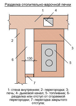
In the walls of the closed space above the stove, two openings with gratings should be provided at different levels, each having a clear cross-sectional area of at least 150 cm2. The retreat is left open or sealed on both sides with bricks or other fireproof materials.
The side walls of the closed chamber are not allowed to be tied to the main masonry of the furnace. The floor in the air gap is lined with bricks one row above the floor level of the room. The width of the setback and the method of insulating walls and partitions in the setbacks are taken in accordance with the data given in Table 3:
Table 3. Types and sizes of indentations
| p/p | Heating stoves | Types of derogation | Distances between stoves and combustible walls or partitions, mm | Methods for protecting combustible structures |
| 1 | 2 | 3 | 4 | 5 |
| 1 | Apartment-type stoves with walls 1/2 brick thick with a fire duration of up to 3 hours. | Open or closed on one side | 130 | Lime or lime-cement plaster 25 mm thick; asbestos cardboard |
| 2 | Same | Closed on both sides | 130 | Brick cladding with a thickness of 1/4 brick on clay mortar or asbestos-vermiculite slabs with a thickness of 40 mm |
| 3 | The same with walls 1/4 brick thick | Open on both sides | 320 | Lime-gypsum plaster 25 mm thick; asbestos-vermiculite slabs 40 mm thick |
| 4 | Heating stoves for long burning | Open | 260 | Same |
| 5 | Stoves and stoves with walls 1/2 brick thick with a fire duration of more than 3 hours. | Open | 260 | The same, or cladding with a thickness of 1/4 brick on clay mortar |
| 6 | Same | Closed | 260 | Brick cladding 1/2 brick thick |
| Metal stoves: | ||||
| 7 | - without lining | Open | 1000 | Plaster 25 mm thick |
| 8 | - with lining | Open | 700 | Same |
The distances from the upper planes of the stove floors to the combustible (or fire-protected) ceilings of the premises must be no less than those indicated in Table 4:
Table 4. Distances from the top of furnace floors to combustible ceilings, mm
| p/p | Furnaces | Ceilings | |
| Not protected from fire | Fireproof | ||
| 1 | 2 | 3 | 4 |
| 1 | Heat-intensive | 350 | 250 |
| 2 | Non-heat-intensive | 1000 | 700 |
| Note: 1. Thickness of the upper ceilings of the furnaces must be at least three rows of bricks. With a smaller thickness, the distances between the top of the stoves and the ceilings increase accordingly. 2. Ceilings can be protected from fire asbestos card thickness 8 mm or thick plaster 25 mm. The protection must be wider than the ceilings by 150 mm on each side. |
|||
The gap between the top of a thick-walled stove and the ceiling can be closed on all sides with brick walls. In this case, the thickness of the upper ceiling of the furnace must be at least 4 rows brickwork, and the combustible ceiling must be protected from fire.
Chimneys and roof structures
Chimneys should be installed above the roof of taller buildings attached to a building with stove heating. The wall thickness of the chimney head above the roof must be at least the thickness of one brick.
The distance from the outer surfaces of chimneys to rafters, sheathing and other roofing parts made of flammable and slow-burning materials should be kept clear:
- from brick or concrete chimneys - at least 130 mm
- from ceramic pipes without insulation - 250 mm
- and for thermal insulation with heat transfer resistance - 0.3 m2 x t°C/W with non-flammable or low-flammable materials - 130 mm
The space between chimneys and roof structures made of non-combustible and low-combustible materials should be covered with non-combustible roofing materials. Gaps between ceilings, walls, partitions and divisions should be filled with non-combustible materials.
The space between the ceiling (in front of the roof) of a heat-intensive stove and the ceiling made of flammable and slow-burning materials may be covered on all sides with brick walls. In this case, the thickness of the furnace ceiling should be increased to four rows of brickwork.