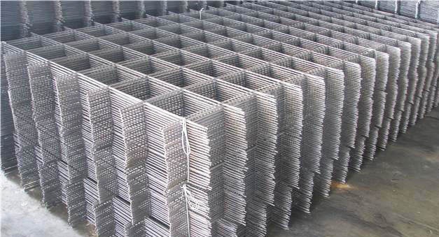
Welded from periodic profile construction reinforcement. The technical parameters of the reinforcement meet the regulatory provisions of GOST 5781-82, and are rolled on modern rolling mills of cyclic or continuous operation. Welded reinforcing mesh is used for strengthening brickwork, during the manufacture of various reinforced concrete building structures and special architectural loaded elements.
The strength calculation is carried out taking into account the direction and magnitude of the maximum forces; it can operate in a constantly loaded state. You can buy welded mesh from A3 reinforcement wholesale in rolls or cards; the specific type of packaging depends on the diameter of the reinforcement.
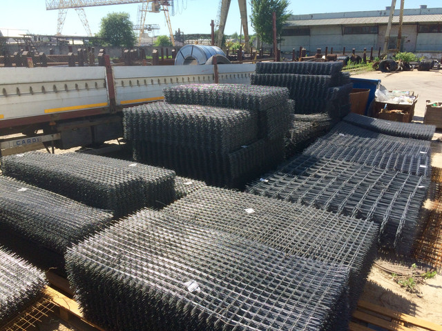
The screed mesh made from A500C reinforcement has an increased coefficient of adhesion to cement-sand mortars, allows you to plaster walls with low strength values, the plaster can withstand significant loads. The metal does not have the effect of residual deformation, the physical characteristics correspond to the specific grade of steel. Reinforcing mesh AIII meets the parameters of GOST 23279-85 and is made of hot-rolled carbon structural steel. Can be used during the construction or repair of concrete roads, to create fences, technological and agricultural fences. Welded reinforcing mesh is sold by weight or by total area. Welding is carried out using the spot method, quality control is carried out by the manufacturer. No more than three uncooked knots per square meter of product are allowed.
GOST 23279-2012 (85) regulates the production of welded mesh (flat or rolled), which are manufactured in factories producing products for construction organizations. Meshes are used to reinforce prefabricated or monolithic concrete or reinforced concrete structures. They can also be used for the construction of various small structures, such as greenhouses, outbuildings, gazebos, and so on.
Welded mesh is made using reinforcing steel (rods or wire), with a thickness of 3 to 40 mm. The most popular are products with cell sizes of 50×50 and 100×100 mm.
1 Classification
Reinforcing mesh is divided according to GOST 23279-2012 (85) in accordance with the following characteristics:
- diameter (section) of rods or wire;
- structural arrangement of reinforcement.
Depending on the diameter of the reinforcement used in production, This parameter is divided:
- lightweight - have transverse and longitudinal rods from 3 to 10 mm;
- heavy - rods located in one direction and having a diameter of 12 mm.
![]()
Another subgroup, which is determined by the direction of the reinforcement:
- working fittings located in one direction (transverse or longitudinal), and distribution fittings in the other;
- working fittings are located in both directions.
1.1 Characteristics
Reinforcing mesh according to GOST 23279-2012 (85) has the following types:
- type 1 (heavy) - the diameter of the working fittings is larger than that of the distribution fittings;
- type 2 (heavy) - there is working reinforcement in both directions;
- type 3 (heavy) - the working fittings are located in the transverse direction and their diameter is larger than that of the distribution fittings;
- type 4 (light) - transverse rods are located across the entire width of the mesh;
- type 5 (light) - has offset transverse rods.
Meshes are produced in accordance with GOST 23279-2012 (85), in flat or roll form.
2 Options
The pitch of the rods in the same direction is the distance between them and it should be the same over the entire area. For heavy meshes of the first type, it is allowed to have an additional step of transverse rods at the edge of the product, which can be equal to 100, 200 and 300 mm.
Lightweight reinforcing mesh can have an additional step in the longitudinal direction at the edges or cutting points (cutting is carried out using special scissors, which can be read about separately). The additional pitch of the rods located longitudinally can have dimensions from 50 mm to a given cell size (50 × 50, 100 × 100 mm), while at the edge it should be a multiple of 10 mm, and in places of cutting 50 mm.
The transverse components of the reinforcing mesh can have an additional step from 50 to 250 mm, with a multiplicity of 10 (50×50, 100×100 mm).
Lightweight reinforcement made in one strip, may be with release of longitudinal rods from 25 to 250 mm (multiples of 5). For transverse values, values of 15, 20 and 30 mm, or from 25 to 100 mm (with a multiple of 25) are allowed. Such outlets are suitable for cells with dimensions of 50×50, 100×100, 100×250 mm.
2.1 Dimensions
These parameters are presented in the following form: 50x50x4, 100x100x5. From the numbers you can determine that the cell is a square, the sides of which are 5 (10) cm, and the diameter of the rod is 4 (5) mm, according to the examples above.
2.2 Weight
2.3 Technical requirements
Welded metal mesh made of reinforcing steel in accordance with GOST 23279-2012 (85) and specific working drawings, as well as accompanying technological documentation.
Working reinforcement in heavy meshes is made of class A-III steel with a rod cross-section of 10-40 mm. In some cases, the use of steel is allowed A-I diameter 10-32 mm.
Heavy mesh distribution fittings (type 1) are made from steel A-I II (6-16 mm), and in type 3 - steel A-III (10-16 mm) and steel A-I (6-16 mm).
For light meshes, steel class B500C (4-5 mm), reinforcing wire made from steel class BP-1 (3-5 mm) and reinforcement made from steel grades A-III and A-I (6-10 mm) are used.
Distribution fittings can be steel B500S with a diameter of 4-5 mm and wire B-l diameter 3-5 mm.
The connection of the rods at their intersections is carried out using resistance spot welding, the operating modes of which must comply with regulatory documents.
In products made using steel grades A-I, V mandatory, all intersections of the rods must be fastened. When assembling a product from rods and wires, connection of intersections by welding is allowed through one or two in a checkerboard pattern. In this case, the two rods running along the edges of the product must be fastened without fail.
A maximum of two non-welded intersections (using clamps) per area of 1 m² is allowed out of the required number of connections.
2.4 Labeling, transport and storage
Data on the product packaged in bags or rolls must be indicated on two metal or plywood tags, which are attached on two different sides.
The total weight of one packaged unit must not exceed three tons. The nets in the bags are tied with soft wire in four places, and the rolls in three.
The information on the tags indicates the following:
- name (trademark) of the enterprise that manufactured the product;
- type ( symbol) products;
- number of units in the package;
- package (roll) weight in tons;
- production date and batch number.
During transportation and loading and unloading operations, rules must be followed safety precautions, and also observe precautions aimed at protecting the product from mechanical damage.
Storage is permissible in indoor areas with distribution by grade and in stacks, the height of which does not exceed 2 meters. Rolls can be folded into tiers, the number of which does not exceed 3. When forming large quantity stacks, a free passage must be left between them, the width of which is at least 0.5 m.
2.5 How is reinforcing mesh produced? (video)
WELDED REINFORCEMENT MESH
FOR REINFORCED CONCRETE
STRUCTURES AND PRODUCTS
GENERAL TECHNICAL CONDITIONS
GOST 23279-85
STATE COMMITTEE OF THE USSR
ON CONSTRUCTION AFFAIRS
STATE STANDARD OF THE USSR UNION
By Decree of the USSR State Committee for Construction Affairs dated November 28, 1984 No. 194, the implementation period was establishedfrom 01.01.86
Failure to comply with the standard is punishable by law
This standard applies to welded flat and rolled meshes (hereinafter referred to as meshes), manufactured at construction industry enterprises from reinforcing steel with diameters from 3 to 40 mm inclusive, with rods arranged in two mutually perpendicular directions and intended for reinforcement of prefabricated and monolithic reinforced concrete structures and products.
1. CLASSIFICATION
1.1. Meshes are divided: according to the diameters of the rods; according to the location of the working reinforcement. 1.2. Depending on the diameter of the rods, meshes are divided into heavy and light. 1.2.1. Heavy meshes include meshes that have rods with a diameter of 12 mm or more in one direction. 1.2.2. Lightweight ones include meshes with longitudinal and transverse rods with a diameter of 3 to 10 mm inclusive.1.3. According to the location of the working reinforcement, the grids are divided: with working reinforcement in one direction (longitudinal or transverse) and distribution reinforcement in the other direction; with working reinforcement in both directions.2. TYPES, MAIN PARAMETERS AND DIMENSIONS
2.1. Meshes are made of the following types (drawings 1 and 2): 1 - heavy with working reinforcement in the longitudinal direction, the diameter of which is greater than the diameter of the distribution fittings; 2 - heavy with working reinforcement in both directions; 3 - heavy with working reinforcement in the transverse direction, diameter which is larger than the diameter of the distribution reinforcement; 4 - light with transverse rods across the entire width of the mesh; 5 - light with offset transverse rods. 2.2. Meshes are made flat or rolled. Light meshes with longitudinal rods made of reinforcing wire with diameters from 3 to 5 mm inclusive are made in rolls. 2.3. The meshes must have rods of the same diameter in the same direction.2.4. Grids are made with square or rectangular cells.2.5. The diameters of the working reinforcement of the meshes are assigned based on the condition of the cross-sectional area of the reinforcement required by calculation.2.6. The ratio of the smaller diameter of the rod to the larger one must be at least 0.25.2.7. The main parameters of the grids are given in table 2.8. The distance between the rods - the main pitch of the rods in one direction should be taken the same. 2.8.1. In heavy meshes of type 1, for transverse rods at the edge of the mesh, an additional step of 100, 200 and 300 mm is allowed. 2.8.2. In light meshes, in addition to the main step of the rods in the longitudinal direction, it is allowed to use an additional step at the edges of the mesh, as well as at the point of cutting. The additional step of longitudinal rods is taken from 50 mm to the size of the main step, a multiple of 10 mm at the edge of the mesh and a multiple of 50 mm at the cutting point mesh. The additional pitch of the transverse rods is from 50 to 250 mm in multiples of 10 mm. 2.9. The dimensions of the outlets of the longitudinal and transverse rods should be taken equal to 25 mm or multiples of 25 mm in accordance with those indicated in the table. In light meshes made in one strip, the dimensions of the outlets of the longitudinal rods can be taken from 30 to 200 mm, a multiple of 5 mm, and the dimensions of the transverse outlets rods - equal to 15, 20 and 30 mm, as well as from 25 to 100 mm in multiples of 25 mm.Heavy mesh
Lightweight mesh
Grid Options
|
Grid view |
Grid type |
Grid width |
Mesh length |
Rod diameters |
Distance between rods (in axes) - pitch of rods |
Rod outlet sizes |
||
|
longitudinal |
transverse |
transverse |
longitudinal |
From 650 to 3050 |
From 850 to 9000 |
From 850 to 5950 |
From 850 to 3050 |
From 850 to 6250 |
From 650 to 3800 |
From 850 to 9000 or up to roll length |
From 3950 to 9000 or up to roll length |
2.10. Grids are designated by marks of the following structure
Where x is the designation of the mesh type (clause 2.1); C - letter designation of the name of the welded mesh (with the addition of the index “p” - Cp) for rolled mesh; d, d 1 - diameter of longitudinal and transverse bars, respectively, indicating the class of reinforcing steel; b, l - respectively, the width and length of the mesh in centimeters. In the brand of the mesh, the following is additionally given: for light meshes, as well as heavy meshes of type 3 with a main pitch of longitudinal rods of 400 mm after the diameter of the rods (through a dash), the value of the pitch of the rods in millimeters; for meshes with additional pitch - respectively above or below the line, the value of the additional pitch of longitudinal or transverse rods in millimeters (in brackets). For meshes with the dimensions of the outlets of transverse and longitudinal rods differing from 25 mm, the mesh brand is added after indicating the mesh length
Where a 1, a 2 are the values of the releases of the longitudinal rods (for a 1 = a 2, only one value is given in millimeters); a is the value of the releases of the transverse rods in millimeters. Examples of symbols: heavy mesh type 1 with longitudinal bars made of class A-III reinforcing steel with a diameter of 25 mm, with a pitch of 200 mm and with transverse bars made of class A-III reinforcing steel with a diameter of 10 mm, with a pitch of 600 mm, a width of 2050 mm and 6650 mm long, with 25 mm longitudinal and transverse rods:
![]()
flat light mesh type 4 with longitudinal rods made of reinforcing steel class A-IIIC with a diameter of 10 mm and transverse rods made of reinforcing wire class BP-I with a diameter of 5 mm, with a pitch of longitudinal and transverse rods of 100 mm, a width of 2550 mm and a length of 6050 mm, with releases of longitudinal and transverse rods 25 mm:
![]()
rolled mesh type 5 with longitudinal and transverse rods made of reinforcing wire of class BP-I with a diameter of 5 mm, with a main pitch of longitudinal rods of 200 mm and an additional pitch of 100 mm, with a pitch of transverse rods of 150 mm, a width of 2340 mm and a length of 120,000 mm, with outlets longitudinal rods 125 and 175 mm, with releases of transverse rods 20 mm:
3. TECHNICAL REQUIREMENTS
3.1. Meshes should be manufactured in accordance with the requirements of this standard according to working drawings and technological documentation approved in the prescribed manner. 3.2. As working reinforcement in heavy meshes, hot-rolled reinforcing steel rods of class A-III with diameters of 12-40 mm and thermomechanically strengthened reinforcing steel of class At-IIIC with diameters of 12-18 mm should be used. During feasibility studies, the use of hot-rolled rods as working reinforcement is allowed reinforcing steel classes A-II and A-I with diameters of 12-32 mm.3.3. As distribution reinforcement in heavy meshes of type 1, reinforcing steel of class A-III and At-IIIC with diameters of 6-16 is used, in meshes of type 3 - reinforcing steel of class A-II with diameters of 10-16 mm and class A-I with diameters of 6-16 mm.3.4. Light mesh should be made from reinforcing wire of class BP-I with diameters of 3-5 mm, hot-rolled rod reinforcing steel of classes A-III and A-I with diameters of 6-10 mm. It is allowed to use reinforcing wire of class B-I with diameters of 3-10 mm as distribution reinforcement. 5 mm.3.5. The grades of reinforcing steel must correspond to the grades established project documentation(in accordance with the requirements of building codes and regulations for the design of concrete and reinforced concrete structures, depending on the operating conditions of the structures) and specified in the order for the production of meshes.3.6. Reinforcing steel must meet the requirements: rod hot-rolled reinforcing steel of classes A-III, A-II and A-I - GOST 5781-82; rod thermomechanical strengthened reinforcing steel of class At-IIIC - GOST 10884-81; reinforcing wire of classes BP-I and B-I - GOST 6727-80.3.7. Cross-shaped connections of rods in meshes should be carried out by resistance spot welding in accordance with the requirements of GOST 14098-85. Welding modes must comply with the requirements of SN 393-78.3.8. In meshes with working reinforcement made of smooth rod reinforcing steel of class A-I, all intersections of the rods must be welded. In meshes with working reinforcement of a periodic profile (rod and wire), it is allowed to weld the intersections of rods through one or two intersections in a checkerboard pattern, if in working There are no special instructions in the drawings. In the reinforcing mesh, no more than two unwelded intersections of rods are allowed in an area of 1 m 2 of the mesh from among the intersections subject to welding. 3.9. Rods at welding points during tensile testing (weakened at intersections and joints) must have a breaking force or temporary tensile strength not lower than that required by GOST 10922-75.3.10. Requirements for the shear strength of welded joints of rods are in accordance with GOST 10922-75. If equal strength requirements are not imposed on welded joints of bars made of reinforcing steel of periodic profile located in two or one direction, then the rejection load during shear testing should be at least 50 % tensile strength of reinforcing wire or tensile strength of reinforcing steel of smaller diameter.3.11. Cross-shaped connections of the mesh rods should not be destroyed by impact when the meshes are freely dropped from a height of 1 m.3.12. Butt connections of reinforcing steel bars should be made using contact butt welding according to GOST 14098-85. Welding modes - according to SN 393-78. Working reinforcement on a rod length of 6 m should not have more than two butt joints, and on a rod length of 12 m - more than three butt joints. Butt joints of rods of the same direction within a step reinforcement in the other direction is allowed through at least three bars.3.13. The values of the relative settlement in cross-shaped joints of rods (in fractions of the smaller diameter of the welded rods) should be for reinforcing steel classes: A - I from ........................... ......................... from 0.16 to 0.5 A - III, A t-IIIC and A - II. ........................... from 0.2 to 0.8 Bp - I and B - I ...... ........................................ from 0.2 to 0.53.14. The values of actual deviations of the geometric parameters of the meshes should not exceed the limits specified in GOST 10922-75.3.15. Longitudinal and transverse rods in meshes must be straight. The values of actual deviations from the straightness of the rods should not exceed 6 mm over a rod length of 1 m.4. ACCEPTANCE RULES
4.1. Acceptance of meshes should be carried out in batches in accordance with the requirements of GOST 10922-75 and this standard.4.2. In each mesh or roll selected from the batch, the following are additionally checked: the dimensions of the outlets; the straightness of the rods; the amount of draft of the rods. 4.3. If unsatisfactory test results are obtained for at least one of the indicators, a repeat test is carried out on a double sample. The results of the re-inspection apply to the entire batch. If, during the re-inspection, at least one mesh does not meet the requirements of GOST 10922-75 and this standard, all meshes are subject to piece-by-piece acceptance.5. CONTROL METHODS
5.1. Methods for monitoring and testing meshes must comply with those established by GOST 10922-75 and this standard. 5.2. The width and length of flat mesh, the pitch of longitudinal and transverse rods, the dimensions of the outlets, the straightness of the rod and the difference in the length of the diagonals, as well as the width of the rolled mesh, the pitch of its longitudinal and transverse rods, the dimensions of the outlets and the straightness of the transverse rods are checked with a tape measure according to GOST 7502-80 or metal ruler according to GOST 427-75.5.3. Cross-shaped connections are checked for impact at the mesh production and packaging stations by freely dropping the meshes from a height of 1 m onto concrete base or on metal pads.6. MARKING, TRANSPORTATION AND STORAGE
6.1. Flat meshes must be tied into bags. The weight of the package should not exceed 3 tons.6.2. A package of mesh must be tied with soft wire in at least four places, and a roll of mesh - in at least three places.6.3. At least two metal or plywood tags must be attached to each bag and roll of mesh, indicating: the name or trademark of the manufacturer; the symbol of the mesh according to clause 2.10; the number of mesh in the package; the weight of the package or roll in tons; number batch and date of manufacture. Tags must be attached to different sides of the bag and roll. 6.4. Each batch of mesh supplied by specialized factories of reinforcing products must be accompanied by a quality document, which indicates: the name and address of the manufacturer; number and date of issue of the document; batch number; name of the products indicating their brands and quantity in the batch; date of manufacture. The document must be signed by the employee responsible for technical control of the manufacturer.6.5. Nets should be transported in a horizontal position. When loading, transporting and unloading nets, measures must be taken to ensure their safety from damage. Methods for performing loading and unloading operations must comply with the stipulated safety rules in construction.6.6. Nets should be stored indoors. Packages of mesh should be stored separately by brand in stacks no more than 2 m high. Rolls of mesh should be stored in no more than three tiers. When storing nets between stacks, a free passage with a width of at least 0.5 m must be provided.6.7. During storage and transportation, each package must be supported by wooden pads and pads with a thickness of at least 30 mm. The pads under the nets should be laid on a dense, carefully leveled base. When storing nets in stacks, the spacers between the bags along the height of the stack should be located vertically, one above the other.GOST 23279-2012
INTERSTATE STANDARD
WELDED REINFORCEMENT MESH FOR REINFORCED CONCRETE STRUCTURES AND PRODUCTS
General technical specifications
Welded reinforcing meshes for reinforced concrete structures and products. General specifications
MKS 91.190
Date of introduction 2013-07-01
Preface
The goals, basic principles and basic procedure for carrying out work on interstate standardization are established by GOST 1.0-92 "Interstate standardization system. Basic provisions" and GOST 1.2-2009 "Interstate standardization system. Interstate standards, rules, recommendations for interstate standardization. Rules for development, adoption, application, renewal and cancellation."
Standard information
1 DEVELOPED by the Russian Academy of Engineering
2 INTRODUCED by the Technical Committee for Standardization TC 465 "Construction"
3 ADOPTED by the Interstate Scientific and Technical Commission for Standardization, Technical Regulation and Conformity Assessment in Construction (Appendix B to the Protocol dated June 4, 2012 N 40)
The following voted for the adoption of the standard:
Short name of the country according to MK (ISO 3166) 004-97 | Abbreviated name of the national construction management body |
|
Azerbaijan | State Committee for Urban Planning and Architecture |
|
Ministry of Urban Development |
||
Kyrgyzstan | Gosstroy |
|
Ministry of Construction and Regional Development |
||
Ministry of Regional Development |
||
Tajikistan | Agency for Construction and Architecture under the Government |
|
Uzbekistan | Gosarchitectstroy |
4 By Order of the Federal Agency for Technical Regulation and Metrology dated November 29, 2012 N 1306-st, the interstate standard GOST 23279-2012 was put into effect as a national standard Russian Federation from July 1, 2013
5 INSTEAD GOST 23279-85
Information about changes to this standard is published in the annual information index "National Standards", and the text of changes and amendments is published in the monthly information index "National Standards". In case of revision (replacement) or cancellation of this standard, the corresponding notice will be published in the monthly information index "National Standards". Relevant information, notices and texts are also posted in information system for public use - on the official website Federal agency on technical regulation and metrology on the Internet
1 Application area
1 Application area
This standard applies to welded flat and rolled meshes (hereinafter referred to as meshes), manufactured at construction industry enterprises from reinforcing steel with diameters from 3 to 40 mm inclusive, with rods located in two mutually perpendicular directions, and intended for reinforcing prefabricated and monolithic reinforced concrete structures and products.
2 Normative references
This standard uses normative references to the following standards:
GOST 427-75 Metal measuring rulers. Specifications
GOST 5781-82 Hot-rolled steel for reinforcement of reinforced concrete structures. Specifications
GOST 6727-80 Cold-drawn low-carbon steel wire for reinforcement of reinforced concrete structures. Specifications
GOST 7502-98 Metal measuring tapes. Specifications
GOST 10922-90 * Welded reinforcement and embedded products, welded connections of reinforcement and embedded products of reinforced concrete structures. General technical conditions
________________
* The document is not valid on the territory of the Russian Federation. GOST 10922-2012 is valid, hereinafter in the text. - Database manufacturer's note.
GOST 14098-91 Welded connections of reinforcement and embedded products of reinforced concrete structures. Types, designs and sizes
Note - When using this standard, it is advisable to check the validity of the reference standards in the public information system - on the official website of the Federal Agency for Technical Regulation and Metrology on the Internet or using the annual information index "National Standards", which was published as of January 1 of the current year, and according to the relevant issues of the monthly information index "National Standards" for the current year. If the reference standard is replaced (changed), then when using this standard you should be guided by the replacing (changed) standard. If the reference standard is canceled without replacement, then the provision in which a reference is made to it is applied in the part that does not affect this reference.
3 Classification
3.1 Grids are divided into:
- by rod diameters;
- according to the location of the working fittings.
3.2 Depending on the diameter of the rods, meshes are divided into heavy and light.
3.2.1 Heavy meshes include meshes that have rods with a diameter of 12 mm or more in one direction.
3.2.2 Lightweight includes meshes with longitudinal and transverse rods with a diameter of 3 to 10 mm inclusive.
3.3 Based on the location of the working reinforcement, the meshes are divided into:
- with working fittings in one of the directions (longitudinal or transverse) and distribution fittings in the other direction;
- with working fittings in both directions.
4 Types, main parameters and dimensions
4.1 Meshes are made of the following types (see Figures 1 and 2):
- type 1 - heavy with working fittings in the longitudinal direction, the diameter of which is greater than the diameter of the distribution fittings;
- type 2 - heavy with working fittings in both directions;
- type 3 - heavy with working fittings in the transverse direction, the diameter of which is greater than the diameter of the distribution fittings;
- type 4 - lightweight with transverse rods across the entire width of the mesh;
- type 5 - lightweight with offset transverse rods.
Figure 1 - Heavy mesh
Type 2
Type 3
Figure 1 - Heavy mesh
Figure 2 - Light mesh
Type 5
Figure 2 - Light mesh
4.2 Meshes are made flat or rolled.
Light meshes with longitudinal bars made of reinforcing steel with diameters from 3 to 5 mm inclusive are produced in rolls.
4.3 Nets must have rods of the same diameter in the same direction.
4.4 Grids are made with square or rectangular cells.
4.5 The diameters of the working reinforcement of the meshes are assigned based on the condition of the cross-sectional area of the reinforcement required by calculation.
4.6 The ratio of the smaller diameter of the rod to the larger one must be at least 0.25.
4.7 The main parameters of the grids are given in Table 1.
Table 1 - Grid parameters
In millimeters
Grid view | Grid type | Grid width | Mesh length | Rod diameters | Distance between rods (in axes) - pitch of rods | Rod release sizes |
||
longitudinal | transverse | transverse | longitudinal and |
|||||
From 650 to 3050 | From 850 to 9000 | Multiples of 25 |
||||||
From 850 to 5950 | Multiples of 25 |
|||||||
From 850 to 3050 | From 850 to 6250 | |||||||
From 650 to 3800 | From 850 to 9000 or up to roll length | 100 (150) | 100 (75) | |||||
From 3950 to 9000 or up to roll length | ||||||||
* It is allowed to use rod spacing of 100 and 300 mm in the grids of standard design documentation for reinforced concrete structures. Notes 1 Heavy meshes of type 1 with a width of 1500 to 3050 mm with longitudinal rods with diameters of 36 and 40 mm and type 3 with a length of 3050 to 6250 mm are produced using single-point machines and suspended welding tongs before the development of automated equipment production. 2 By agreement with the manufacturer, the use of heavy mesh type 1 and light flat mesh with a length of up to 11500 mm is allowed. 3 In lightweight mesh type 5, the length of the transverse rods is from 0.85 to 0.90 of the mesh width. 4 The distances between the longitudinal and transverse rods of light mesh, indicated in brackets, may be accepted during a feasibility study. |
||||||||
________________
Probably an error in the original. Should read: See 4.9 (letter of Rosstandart TK 465 “Construction” dated December 27, 2016 N TK-736/2016). - Database manufacturer's note.
4.8 The distance between the rods - the main step of the rods in one direction - should be taken the same.
4.8.1 In heavy meshes of type 1, for transverse rods at the edge of the mesh, an additional step of 100 is allowed; 200 and 300 mm.
4.8.2 In light meshes, in addition to the main step of the rods in the longitudinal direction, it is allowed to use an additional step at the edges of the mesh, as well as at the point of cutting it.
The additional pitch of the longitudinal rods is taken from 50 mm to the size of the main step, a multiple of 10 mm at the edge of the mesh and a multiple of 50 mm at the point where the mesh is cut.
The additional pitch of the transverse rods is taken from 50 to 250 mm, a multiple of 10 mm.
4.9 The dimensions of the releases of longitudinal and transverse rods should be taken equal to or multiples of 25 mm in accordance with those indicated in Table 1.
In light meshes made in one strip, the dimensions of the outlets of the longitudinal rods can be taken from 25 to 200 mm, multiples of 5 mm, and the dimensions of the outlets of the transverse rods - equal to 15; 20 and 30 mm, as well as from 25 to 100 mm, multiples of 25 mm.
4.10 Grids are designated by marks of the following structure
where is the designation of the mesh type (see 2.1);
- designation of the name of the welded mesh (with the addition of an index for rolled meshes);
, - diameters of longitudinal and transverse bars, respectively, indicating the class of reinforcing steel;
, - width and length of the grid, cm, respectively.
In the designation of the mesh brand, the following is additionally given:
- for light meshes, as well as heavy meshes of type 3 with a main pitch of longitudinal rods of 400 mm after the diameter of the rods (through a dash) - the value of the pitch of the rods in millimeters;
- for meshes with additional spacing - above the line or below the line, respectively, the value of the additional spacing of longitudinal or transverse rods in millimeters (in parentheses).
For meshes with outlet sizes of transverse and longitudinal rods different from 25 mm, the designation of the mesh brand after the designation of the mesh length is supplemented with the following designation:
where , are the values of the releases of the longitudinal bars (only one value is given), mm;
- the value of the releases of the transverse rods, mm.
Examples of symbols:
- heavy mesh type 1 with longitudinal bars made of reinforcing steel class A500C with a diameter of 25 mm, with a pitch of 200 mm and with transverse bars made of reinforcing steel class A500C with a diameter of 10 mm, with a pitch of 600 mm, width 2050 mm and length 6650 mm, with longitudinal outlets and cross bars 25 mm:
Flat light mesh type 4 with longitudinal bars made of reinforcing steel class A500C with a diameter of 10 mm and transverse bars made of reinforcing steel B500C with a diameter of 5 mm, with a pitch of longitudinal and transverse bars of 100 mm, a width of 2550 mm and a length of 6050 mm, with releases of longitudinal and transverse bars 25mm:
Rolled mesh type 5 with longitudinal and transverse bars made of reinforcing steel class B500C with a diameter of 5 mm, with a main pitch of longitudinal bars of 200 mm and an additional pitch of 100 mm, with a pitch of transverse bars of 150 mm, a width of 2340 mm and a length of 120,000 mm, with releases of longitudinal bars 125 and 175 mm, with 20 mm crossbar outlets:
5 Technical requirements
5.1 Meshes should be manufactured in accordance with the requirements of this standard according to working drawings and technological documentation approved in the prescribed manner.
5.2 As working reinforcement in heavy meshes, reinforcing steel bars of classes A500C, A600C and A400 (A-III) with a diameter of 10-40 mm should be used.
During feasibility studies, the use of hot-rolled reinforcing steel bars of class A240 (A-l), with a diameter of 10-32 mm, as working reinforcement is allowed.
5.3 As distribution reinforcement in heavy meshes of type 1, reinforcing steel of classes A400 (A-III), A500C, B500C and A600C with diameters of 6-16 mm is used, in meshes of type 3 - reinforcing steel of classes A400 (A-III), A500C, B500C and A600C with a diameter of 10-16 mm and A240 (A-l) with a diameter of 6-16 mm.
5.4 Lightweight mesh should be made from reinforcing steel of class B500C with a diameter of 4-5 mm, reinforcing wire of class Bp-I with a diameter of 3-5 mm and rod reinforcing steel of classes A400 (A-III), A500C, B500C and A240(A-I) with a diameter of 6- 10 mm.
As distribution fittings, it is allowed to use reinforcing steel of class B500C with a diameter of 4-5 mm and reinforcing wire class B-l with a diameter of 3-5 mm.
5.5 The grades of reinforcing steel for the production of meshes must correspond to the grades established by the design documentation (in accordance with the requirements of building codes and regulations for the design of concrete and reinforced concrete structures, depending on the operating conditions of the structures), specified in the order for the production of meshes.
5.6 Reinforcing steel must meet the requirements:
- rod reinforcing steel classes A400 (A-III) and A240 (A-I) - GOST 5781;
- rod reinforcing steel of classes A500C and B500C - active regulatory documents*;
_______________
* In the Russian Federation, GOST R 52544 applies to reinforcing steel of classes A500C and B500C.
- rod reinforcing steel class A600C - current regulatory documents;
- reinforcing wire of classes Bp-I and B-l - GOST 6727.
5.7 Cross-shaped connections of rods in meshes should be carried out by resistance spot welding in accordance with GOST 14098.
Welding modes must comply with the requirements of current regulatory documents.
5.8 In meshes with working reinforcement made of smooth bar reinforcing steel of class A240 (A-l), all intersections of the rods must be welded.
In meshes with working reinforcement of a periodic profile (rod and wire), it is allowed to weld the intersections of the rods through one or two intersections in a checkerboard pattern, if there are no special instructions in the working drawings. The two outermost bars in the meshes must be welded at all intersections
In the reinforcing mesh, no more than two unwelded intersections of rods are allowed in an area of 1 m of the mesh from among the intersections subject to welding.
5.9 The breaking force or temporary tensile strength of rods at welding points during a tensile test (weakened at intersections and joints) must not be lower than required by GOST 10922.
5.10 Requirements for the shear strength of welded joints of rods - in accordance with GOST 10922.
If the welded joints of bars made of reinforcing steel of periodic profile, located in two or one direction, are not subject to equal strength requirements according to GOST 10922, then the rejection load during shear testing should be at least 30% of the tensile strength of the reinforcing wire or the lesser tensile strength of the reinforcing steel diameter
5.11 Cross-shaped connections of the net rods should not be destroyed by impact when the nets are freely dropped from a height of 1 m.
5.12 Butt joints of reinforcing steel bars should be made by contact butt welding in accordance with GOST 14098.
Welding modes - according to current regulatory documents.
Working reinforcement on a rod length of 6 m should not have more than two, and on a rod length of 12 m - more than three butt joints.
Butt connections of rods in one direction within the reinforcement pitch in another direction are allowed through at least three rods.
5.13 The values of relative settlement in cross-shaped joints of rods (in fractions of the smaller diameter of the welded rods) should be for reinforcing steel classes A240 (A-l), A400 (A-III), B500C, A500C and A600C from 0.2 to 0.5.
5.14 The values of actual deviations of the geometric parameters of the grids should not exceed the limits specified in GOST 10922.
5.15 Longitudinal and transverse rods in meshes must be straight.
The values of actual deviations from the straightness of the rods should not exceed 6 mm over a rod length of 1 m.
6 Acceptance rules
6.1 Grids are accepted in batches in accordance with the requirements of GOST 10922 and this standard.
6.2 In each mesh or roll selected from the batch, the following is additionally checked:
- sizes of releases;
- straightness of the rods;
- the amount of settlement of the rods.
6.3 If unsatisfactory test results are obtained for at least one of the indicators, a re-check is carried out on a double sample. The results of the re-inspection are applied to the entire batch.
If, during re-checking, at least one mesh does not meet the requirements of GOST 10922 and this standard, all meshes are subject to piecemeal acceptance.
7 Control methods
7.1 Methods for monitoring and testing meshes must comply with those established by GOST 10922 and this standard.
7.2 The width and length of flat mesh, the pitch of longitudinal and transverse rods, the dimensions of the outlets, the straightness of the rod and the difference in the length of the diagonals, as well as the width of the rolled mesh, the pitch of its longitudinal and transverse rods, the dimensions of the outlets and the straightness of the transverse rods are checked with a tape measure in accordance with GOST 7502 or a metal one ruler according to GOST 427.
7.3 Cross-shaped connections for impact are checked at the mesh production and packaging stations by freely dropping the meshes from a height of 1 m onto a concrete base or metal pads.
8 Labeling, transportation and storage
8.1 Flat meshes must be bundled. The weight of the package should not exceed 3 tons.
8.2 A package of mesh must be tied with soft wire in at least four places, and a roll of mesh in at least three places.
8.3 At least two metal or plywood tags must be attached to each bag and roll of nets, indicating:
- name or trademark of the manufacturer;
- symbol of grids according to 4.10;
- number of meshes in the package;
- mass of the package or roll, t;
- batch number and date of manufacture.
Tags must be attached to different sides of the bag and roll.
8.4 Each batch of mesh supplied by specialized enterprises of reinforcing products must be accompanied by a quality document, which indicates:
- name and address of the manufacturer;
- number and date of issue of the document;
- batch number;
- name of the products, indicating their brands and number in the batch;
- date of manufacture.
The document must be signed by an employee responsible for technical control of the manufacturer.
8.5 Nets should be transported horizontally.
When loading, transporting and unloading nets, measures must be taken to ensure their safety from damage. Methods for performing loading and unloading operations must comply with safety regulations provided for in construction.
8.6 Nets must be stored indoors. Packages of mesh should be stored separately by brand in stacks no more than 2 m high. Rolls of mesh should be stored in no more than three tiers. When storing nets between stacks, a free passage of at least 0.5 m in width must be provided.
8.7 During storage and transportation, each package must be supported by wooden pads and pads with a thickness of at least 30 mm.
The pads under the nets should be laid on a dense, carefully leveled base. When storing nets in stacks, the spacers between the bags along the height of the stack should be located vertically, one above the other.
Electronic document text
prepared by Kodeks JSC and verified against:
official publication
M.: Standartinform, 2013